8
1
6
7
8
5
4
3
1
2
+
+
+
GND
SIG
+B
VSS
VDD
RESET_SW
AUDIO_IN
VIDEO
SEL1
SEL0
DATA IN
SA
XB
SDATA INT
Ready
TXD
YB
YA
RC01
RC00
RC11
RC10
RD13
RD12
RD11
RD10
RD17
RD16
RD15
RD14
SRD04
SRD05
SRD06
SRD07
SRD00
SRD01
SRD02
SRD03
SRC00
SRC01
SRC11
SRC10
VCC
VCC
OUT
R1
IN
R2
OUT
T2
V-
C2-
C2+
C1-
V+
C1+
OUT
R2
IN
T2
IN
T1
IN
R1
OUT
T1
GND
VCC
IN-0A
IN-1A
IN-2A
IN-2B
IN-0B
IN-1B
OUT-1
OUT-2
OUT-0
VCC
VCC
VCC
VCC
VCC
D-GND
A-GND
A-GND
A-GND
VEE
VEE
VEE
D-VCC
SW1
SW2
+ -
IN
I-IN
OUT
V+
V-
+ -
IN
I-IN
OUT
V+
V-
+ -
IN
I-IN
OUT
V+
V-
V
H
PR
R
PB
B
Y
CV
G
4
3
2
1
1
GND
C
B
A
B
A
C
VCC
H
H
H
L
L
L
3
1
2
VDD
TEST
SCL
SDA
VSS
A2
A1
A0
R
L
AUDIO_IN
CG1
AUDIO_IN
CG2
Y0
Y2
Y
Y3
EN
VEE
Y1
GND
VCC
X2
X1
X
X0
X3
10 H L H L
9 H H L L
3 2 1 0
2
T
U
P
N
I
1
G
C
G-SYNC
Cr/Pr
Cb/Pb
Y
VIDEO
S-V
NTR1-30
C1023
C2088
NTQ-53
1E-9
2A-7
1G-5
1H-5
2D-7
2B-7
1B-7
1A-16
NTF1-1
NTF1-3
NTT1-3
NTT1-5
NTT1-1
NTR1-35
NTR1-33
NTR1-31
NTR1-29
NTR1-27
NTR1-25
NTR1-23
NTR1-21
IC5212-3
IC5212-2
IC5212-1
IC7141-1
IC7141-2
2AU-5
2AU-3
2AU-1
2S-1
2S-2
R5216
C5272
C5262
C5263
C5273
R5217
R5218
C5274
C5264
D5203
D5202
D5204
CG2/H-SYNC
V-OUT
SW
H-SW
V-SW
CG1-H
CG2-V
CG2-H
CG1-V
+5V
S-5V
CG1/H-SYNC
C5291
C5271
R5271
R5219
C5251
C5252
D5206
R5291
R5221
C5261
R5223
R5222
R5224
R5226
CG/H-SYNC
CG/V-SYNC
CG1/CG2-SW
AU1001
R2027
Q2006
R103
R2033
Q2004
C2013
C2012
C2011
C103
C102
C101
C114
C113
L102
C112
C111
R3805
C3805
R3815
IC3806
R1063
R1062
C1022
R1061
C1021
RC
PRE AMP
C3807
R3807
R3806
R3832
R3814
C7151
K20G
C7144
C7143
4
1
K10T
NT1R-3
(ONLY HD)
(ONLY HD)
(ONLY HD)
(Composite V)
R107
R106
R104
R102
R101
READY
RXD2
M2/PIN8
M2/PIN7
TXD2
CLK/SDATA
DATA
L1018
L1019
L1022
L1024
L1026
L1021
L1023
1E-1
1E-8
1E-7
1E-6
1E-5
1E-3
1E-2
D1039
D1041
D1042
D1043
D1044
D1047
D1048
D1049
K10EA
K10E
D1046
SW1001
R1058
C1018
R3816
CPU-TXD2
CPU-TXD2
RXD
TXD2
RXD2
CLK/SDATA
READY
DATA
RXD2
MOUSE-TXD
R/C
RXD
MOUSE-TXD
TXD2-DRV
MOUSE/CPU-SW2
M2/SEL1
M2/SEL0
M2/RESET
R3804
R3817
R3818
R3819
D3803
C3809
R3803
C3801
RB3801
R3801
R3821
R3802
X3802
C3808
C3804
C3881
C3803
R3826
D3801
D3802
C3802
R3829
R3828
R3823
R3822
C3812
R3831
R3827
C3811
X3803
R3824
R1057
R1056
1D_4
1D_3
1D_2
D1038
D1037
D1034
D1036
C2009
C2008
C2014
R2029
R2032
R2031
R2028
C2016
R2024
R2026
R2021
Q2003
R2023
R2022
R2019
R2014
R2018
R2017
Q2002
R2016
R2011
Q2001
R2012
R2013
R2009
IN3-SY
IN3-SC
IN3-CR
IN3-CB
R2005
R2004
R2008
IN2-PR
IN2-PB
IN2-CV/Y
C1007
C1017
C106
C107
C109
R122
C104
C108
R123
R124
R126
R108
R109
R111
R112
R113
R114
R1034
R1039
R1038
C1009
R1036
R1042
R1041
C1012
R1037
R1044
R1043
C1014
C1011
C1013
C1016
C1004
C1006
C1008
IN2-R
IN2-B
IN2-G
USB_D+
USB_D-
K10D
C2061
R2061
R2062
R7273
R2070
R1007
R1005
R1001
R2007
R7224
R7223
C5229
K20HA
R5214
C5203
C5202
C5201
C5206
C5204
R5204
R5206
R5207
D5201
R1006
R1016
R1014
D1013
D1012
K20H
D2024
D2026
D2023
R2046
R2047
R2044
L2019
L2018
2H-3
2H-2
2H-1
C7153
C7152
R7148
H-SYNC
POLH
EXIH
POLV
EXIV
VCC
HDRV
CLAMP
VDRV
CPWID
GND
CPSEL
CVEXI
CVPOL
VSYNC IN
VSEPA
(VIDEO IN)
G-SYNC IN
IN
C/HSYNC
HSCTL
V-SYNC
C7145
C7149
C7148
R7147
C7146
D1011
C5208
C5207
1A-9
1A-15
1A-12
R2074
R1008
R1004
NT1P-7
C5011
C5009
C5008
C5007
C5004
C5003
C5006
R2073
R2072
R2071
R2069
R2068
R2067
R2066
R2065
R2064
R2063
K20B
NT1R-35
SVIDEO_Y
SVIDEO_C
NT1R-17
NT1R-1
NT1R-15
NT1R-11
NT1R-7
AV_Y
NT9V
NT5V
NT-5V
NTS5V
NT1P-29
NT1P-27
NT1P-23
NT1P-21
NT1P-17
NT1P-15
NT1P-11
NT1P-9
NT1P-5
NT1P-3
NT1P-1
NT1Q-5
DDC_DATA
DDC_CLK
K10F
L1001
L1002
L1003
L1004
L1006
L1007
L1008
L1009
L1011
L1012
R5018
R5017
CG-B
CG-G
R5233
R5232
MOUSE/CPU-SW2
CG/V-SYNC
CG/H-SYNC
K20A
CG/AV-SW
CG1/CG2-SW
CG/H-SYNC
CG/V-SYNC
V-STATE
1
2
2
6
10
14
18
22
26
30
34
38
42
46
50
54
53
54
NT1Q-51
NT1Q-49
NT1Q-45
NT1Q-43
NT1Q-41
NT1Q-39
NT1Q-33
NT1Q-31
NT1Q-23
NT1Q-27
NT1Q-19
NT1Q-15
NT1Q-13
NT1Q-11
NT1Q-3
2A-6
2A-5
2A-2
DIGITAL-INPUT
C2092
C2083
C5217
C5218
GND
GND
GND
GND
SW2
S-5V
+5V
+5V
+5V
+5V
+5V
S-5V
RX2+
RX2-
RX1+
RX1-
RXO+
RXO-
RXC+
RXC-
C2087
CG/AV_SW
AV_CB
AV_CR
K10R
RB5002
D1006
D1001
D1003
L2009
D2007
D2006
L2008
D2004
D2003
C2003
C2002
R2003
R2002
L2003
L2002
R7229
R7227
C7222
C7221
C5224
H-SYNC
V-SYNC
C7271
C7272
R7293
R7294
C7291
R7266
Q7262
R7267
R1021
R1019
R1022
K10B
D1016
D1014
D1019
D1021
D1018
D1017
D1023
D1022
R1023
R1026
R1027
R1024
D7221
D7222
C1003
C1002
C1001
C5222
C5223
K20DA
K10HA
K10GA
R7222
R7221
C5209
L5202
L5201
C2091
C2081 C2082
D2012
D2009
D2011
D2008
D2013
D5013
D5012
D5011
D5009
D5008
D5007
D5006
D2017
D2016
D2015
D2014
D2002
D2001
D1033
D1032
D1031
D1029
D1028
D1027
D1026
D1024
D1007
D1004
D1002
D1009
D1008
R5231
R5227
R5228
R5229
C5226
C5227
Q5201
Q5202
C5228
Q5204
Q5203
CG-FILTER
CG_FILTER
1A-1
1A-2
1A-3
1A-13
1A-14
1B-1
1B-2
1B-3
1B-5
1B-4
1G-3
1G-2
1H-3
1H-2
2B-1
2B-3
2B-6
2D-5
2D-4
2D-3
CG-B
VSYNC_DET
CG1/CG2_SW
RXD
CPU-TXD2
MOUSE/CPU-SW2
MOUSE/CPU-SW1
R1012
R1009
R1011
R1013
46
42
38
34
26
18
14
6
50
46
42
38
34
26
22
18
14
6
RB5001
R5215
R5213
R5212
R1032
R1033
R1017
R1018
R5209
R5208
R5211
CG1-B
CG1-G
CG1-R
CG2=LOW
CG1=HIGH
CG2-B
CG2-G
CG2-R
CG1-B
CG1-R
CG1-G
S-5V
+5V
SW1
CG-R
CG-B
CG-G
CG-B
C5214
R5021
R5019
R5016
R5014
C2086
C5016
C5211
C5013
C5012
C5212
C5213
54
30
10
2
2
54
50
30
22
10
R/C
S_SWIN
AUDIO-SW2
AUDIO-SW1
CG-R
CG_HSYNC
CG_VSYNC
CG-B
CG-G
CG-R
54
53
2
1
54
53
2
1
CPU-TXD2
AUDIO-L
AUDIO-R
AUDIO-SW2
AUDIO-SW1
RXD
R/C
CG-G
CG-G
CG-R
CG-R
K10P
K10Q
R2041
S-SW
L2013
R2006
C2007
L2012
L2011
R2039
Q5008
Q5007
PC1-R
PC2-R
AV1-R
PC2-L
AV1-L
PC1-L
PC2-R
PC2-L
PC1-R
PC1-L
C5014
R5011
R5009
R5013
R5012
L1013
L1014
L1016
L1017
L2007
R1054
R1053
R1052
R1051
R1049
R1048
R1047
R1046
K10G
K10H
C5221
C5219
C5216
V-SYNC1
H-SYNC1
R1031
R1029
R1028
R5203
R5202
R5201
K10A
V-SYNC2
H-SYNC2
AV-R
AV-L
K20D
R1002
R1003
L2014
L2015
IN3-CV/Y
C2001
C2006
C2004
L2001
L2006
L2004
R2034
R2036
R2001
NT1
47WM
6.3EM
100D
16EM
NT1
NT1
NT1
NT1
NT2
NT1
NT1
NT1
NT1
NT1
NT1
NT1
NT1
NT1
NT1
NT1
NT1
NT1
NT1
NT1
NT1
NT1
NT1
NT1
NT1
NT1
NT1
NT1
NT1
NT1
NT2
NT2
100KC
1/16GJ
CGQY
CJ180
4.7DB
16PM
4.7DB
16PM
CGQY
CJ121
100KC
1/16GJ
100KC
1/16GJ
CGQY
CJ121
4.7DB
16PM
1SS355
1SS355
1SS355
GQFY
KZ0.01
CGQY
CJ180
100KC
1/16GJ
150C
1/16GJ
UGQFY
10KZ1
UGQFY
10KZ1
1SS355
X
10C
1/16GJ
4.7DB
16PM
150C
1/16GJ
X
150C
1/16GJ
1/16GJ100C
U20B24900
0C
1/16GZ
KR
2SC2412
22KC
1/16GJ
1KC
1/16GJ
KR
2SC2412
10WR
16EM
10WR
16EM
10WR
16EM
10WR
16EM
10WR
16EM
10WR
16EM
220D
16EM
GQFY
25KZ0.1
1/8GJ10
220D
16EM
GQFY
25KZ0.1
X
X
X
X
100C
1/16GJ
0C
1/16GZ
GQFY
10KZ1U
100C
1/16GJ
CGQY
CJ220
GQFY
10KZ1U
0C
1/16GZ
0C
1/16GZ
0C
1/16GZ
10KC
1/16GJ
CGQY
CJ100
J30B1260N
0.47BA
16KK
0.47BA
16KK
J10AV040N
NT1
56KC
1/16GJ
22KC
1/16GJ
56KC
1/16GJ
56KC
1/16GJ
22KC
1/16GJ
256G
F34EA
256G
F34EA
256G
F34EA
256G
F34EA
256G
F34EA
256G
F34EA
256G
F34EA
NTY
NTY
NTY
NTY
NTY
NTY
NTY
02DZ20G
02DZ20G
02DZ20G
02DZ20G
02DZ20G
02DZ20G
02DZ20G
02DZ20G
2EAA0010--
J11A00300
02DZ20G
S10B5120N
100C
1/16GJ
GQFY
0.1
25KZ
100C
1/16GJ
100C
1/16GJ
1/16GJ100C
10KC
1/16GJ
33KC
1/16GJ
5.1YG
02DZ
GQFY
10KZ1U
X
GQFY
10KZ1U
;R1HA1034G
R1EA1034G
100C
1/16GJ
0C
1/16GZ
1/16GZ0C
;V11B1240G
V11B0770P
GQFY
10KZ1U
EM1D
1D
EM
EM1D
10KC
1/16GJ
1SS355
1SS355
EM1D
10KC
1/16GJ
10KC
1/16GJ
10KC
1/16GJ
10KC
1/16GJ
EM1D
0C
1/16GZ
100C
1/16GJ
GQFY
10KZ1U
;V11B1240G
V11B0770P
0C
1/16GZ
0C
1/16GZ
0C
1/16GZ
NT1
NT1
NT1
02DZ12YG
02DZ12YG
02DZ12YG
02DZ12YG
X
47WM
16EM
0.1GQFY
25KZ
1KC
1/16GJ
0C
1/16GZ
47KC
1/16GJ
47KC
1/16GJ
10WR
16EM
47KC
1/16GJ
47KC
1/16GJ
1KC
1/16GJ
KR
2SA1037
0C
1/16GZ
22KC
1/16GJ
47KC
1/16GJ
47KC
1/16GJ
22KC
1/16GJ
0C
1/16GZ
KR
2SA1037
1KC
1/16GJ
1KC
1/16GJ
KR
2SA1037
0C
1/16GZ
22KC
1/16GJ
47KC
1/16GJ
75
1/3GJ
75
1/3GJ
10KC
1/16GJ
47WM
6.3EM
47WM
6.3EM
GQFY
25KZ0.1
GQFY
25KZ0.1
GQFY
KZ0.01
1KC
1/16GJ
GQFY
25KZ0.1
GQFY
25KZ0.1
33C
1/16GJ
33C
1/16GJ
33C
1/16GJ
100C
1/16GJ
100C
1/16GJ
100C
1/16GJ
100C
1/16GJ
100C
1/16GJ
100C
1/16GJ
X
X
1KC
1/16GJ
CGQY
CJ33
X
X
1KC
1/16GJ
CGQY
CJ33
X
X
1KC
1/16GJ
CGQY
CJ33
0.1GQFY
25KZ
0.1GQFY
25KZ
0.1GQFY
25KZ
0.1GQFY
25KZ
0.1GQFY
25KZ
0.1GQFY
25KZ
J11B2770N
GQFY
25KZ0.1
X
2.2KC
1/16GJ
0C
1/16GZ
1K
1/10GJ
X
X
GJ75
1/3
X
1/16GZ0C
1/16GZ0C
X
0008--
1AA2EAA
X
X
X
X
X
GQFY
25KZ0.1
10K
1/10GJ
100C
1/16GJ
100C
1/16GJ
-40G
RB051L
X
10K
1/10GJ
10K
1/10GJ
12YG
02DZ
02DZ12YG
J12A00400
02DZ6.2YG
02DZ6.2YG
02DZ6.2YG
10KC
1/16GJ
330C
1/16GJ
1/10GJ100
F34EA256G
F34EA256G
NT1
NT1
NT1
100WM
6.3EM
GQFY
25KZ0.1
3.9KC
1/16GJ
EM1D
EM1D
EM2.2D
1MC
1/16GJ
0.47BA
16KK
RB051L-40G
GQFY
10KZ1U
GQFY
10KZ1U
NT1
NT1
NT1
0.0
1/10GZ
100C
1/16GJ
100C
1/16GJ
NT1
0.47GQFY
10KZ
2.2FA
16KZ
2.2FA
16KZ
2.2FA
16KZ
2.2FA
16KZ
2.2FA
16KZ
2.2FA
16KZ
X
X
X
X
X
X
X
X
X
X
J12B2771N
NT1
NT1
NT1
NT1
NT1
NT1
NT1
NT1
NT1
NT1
NT1
NT1
NT1
NT1
NT1
NT1
NT1
NT1
NT1
NT1
NT1
NT1
J11B4930N
F34DA200G
F34DA200G
F34DA200G
207G
F34EA
207G
F34EA
F34DA200G
F34DA200G
F34DA200G
207G
F34EA
207G
F34EA
1.8KC
1/16GJ
1.8KC
1/16GJ
10KC
1/16GJ
X
J12B2641N
X
X
X
X
X
X
X
X
X
X
X
X
X
X
X
X
X
X
100WM
6.3EM
100WM
6.3EM
GQFY
25KZ0.1
47WM
6.3EM
1UGQFY
10KZ
540G
J11MD
R1HA1044G
6.2YG
02DZ
6.2YG
02DZ
6.2YG
02DZ
F34EA107G
02DZ6.2YG
02DZ6.2YG
F34EA107G
02DZ6.2YG
02DZ6.2YG
X
X
75
1/3GJ
75
1/3GJ
1/8GZ000
1/8GZ000
100C
1/16GJ
100C
1/16GJ
GQFY
25KZ0.1
GQFY
25KZ0.1
X
47WM
6.3EM
GQFY
10KZ1U
100C
1/16GJ
X
X
10KC
1/16GJ
2412KR
2SC
10KC
1/16GJ
GJ75
1/3
GJ75
1/3
GJ75
1/3
J11B3540N
6.2YG
02DZ
6.2YG
02DZ
6.2YG
02DZ
6.2YG
02DZ
6.2YG
02DZ
6.2YG
02DZ
6.2YG
02DZ
6.2YG
02DZ
X
X
GZ0.0
1/10
GZ0.0
1/10
4.7YG
02DZ
4.7YG
02DZ
X
X
X
X
X
1AA2EAA0007--
1AA2EAA0008--
1AA2EAA0008--
15C
1/16GJ
15C
GJ
1/16
47WM
6.3EM
1/8GZ000
1/8GZ000
100WM
6.3EM
100WM
6.3EM
100WM
6.3EM
02DZ6.2YG
02DZ6.2YG
02DZ6.2YG
02DZ6.2YG
02DZ12YG
02DZ15YG
02DZ15YG
15YG
02DZ
02DZ15YG
02DZ15YG
02DZ15YG
02DZ15YG
02DZ12YG
02DZ12YG
02DZ12YG
02DZ12YG
02DZ6.2YG
02DZ6.2YG
02DZ6.2YG
02DZ6.2YG
02DZ6.2YG
02DZ6.2YG
02DZ6.2YG
02DZ6.2YG
02DZ6.2YG
02DZ6.2YG
6.2YG
02DZ
6.2YG
02DZ
6.2YG
02DZ
02DZ12YG
12YG
02DZ
1KC
1/16GJ
10KC
1/16GJ
10KC
1/16GJ
10KC
1/16GJ
CJ56CGQY
CJ56CGQY
2412KR
2SC
2412KR
2SC
CJ56CGQY
2412KR
2SC
2412KR
2SC
X
X
X
X
X
X
X
X
X
X
X
X
X
X
X
X
X
X
X
X
GZ0.0
1/10
GZ0.0
1/10
X
X
R1HA1044G
22C
1/16GJ
22C
1/16GJ
22C
1/16GJ
100C
1/16GJ
100C
1/16GJ
100C
1/16GJ
100C
1/16GJ
10C
1/16GF
10C
1/16GF
10C
1/16GF
GQFY
KZ0.01
100C
1/16GJ
100C
1/16GJ
0C
1/16GZ
0C
1/16GZ
1UGQFY
10KZ
0.47GQFY
10KZ
GQFY
10KZ1U
22WM
16EM
0.47GQFY
10KZ
GQFY
25KZ0.1
47WM
6.3EM
540G
J11MD
540G
J11MD
GJ100
1/10
256G
F34EA
GJ100
1/10
GQFY
KZ0.01
F34EA107G
F34EA107G
GJ100
1/10
2412KR
2SC
2412KR
2SC
10WR
16EM
3.3KC
1/16GJ
3.3KC
1/16GJ
100C
1/16GJ
100C
1/16GJ
F34EA256G
F34EA256G
F34EA256G
F34EA256G
F34EA107G
GZ0.0
1/10
GZ0.0
1/10
GZ0.0
1/10
1/10GZ0.0
470K
GJ
1/10
470K
GJ
1/10
470K
GJ
1/10
470K
GJ
1/10
00400
J12A
00400
J12A
47WM
6.3EM
GQFY
10KZ1U
GQFY
10KZ1U
100C
1/16GJ
100C
1/16GJ
100C
1/16GJ
100C
1/16GJ
100C
1/16GJ
100C
1/16GJ
J11B0990N
J11B0850N
GJ75
1/3
GJ75
1/3
256G
F34EA
256G
F34EA
X
X
X
1/8GZ000
1/8GZ000
1/8GZ000
470K
1/10GJ
470K
1/10GJ
75
1/3GJ
1
2
3
4
5
6
7
8
9
10
11
12
13
14
15
16
3
2
1
1
2
3
5
4
3
2
1
1
2
3
1
2
3
1
2
3
1
2
3
1
2
3
1
2
3
1
2
3
16
15
14
13
12
11
10
9
8
7
6
5
4
3
2
1
28
27
26
25
24
23
22
21
20
19
18
17
16
15
14
13
12
11
10
9
8
7
6
5
4
3
2
1
1
2
3
4
5
6
7
8
9
10
11
12
13
14
15
16
17
18
19
20
21
22
23
24
1
2
3
4
5
6
7
8
9
10
11
12
13
14
15
16
17
18
19
20
21
22
23
24
1
2
3
4
5
1
2
3
4
5
1
2
3
4
5
16
15
14
13
12
11
10
9
8
7
6
5
4
3
2
1
6
5
4
3
2
1
3
2
1
3
2
1
18
17
16
15
14
13
12
11
10
9
8
7
6
5
4
3
2
1
8
7
6
5
4
3
2
1
26
25
24
23
22
21
20
19
18
17
16
15
14
13
12
11
10
9
8
7
6
5
4
3
2
1
3
2
1
1
2
3
3
2
1
1
2
3
3
2
1
1
2
3
3
2
1
1
2
3
3
2
1
1
2
3
24
23
22
21
20
19
18
17
16
15
14
13
12
11
10
9
8
7
6
5
4
3
2
1
3
2
1
3
2
1
5
4
3
2
1
5
4
3
2
1
3
2
1
3
2
1
3
2
1
16
15
14
13
12
11
10
9
8
7
6
5
4
3
2
1
3
2
1
3
2
1
3
2
1
3
2
1
3
2
1
1
14
2
15
3
4
5
6
7
8
9
10
11
12
13
1
2
3
3
2
1
9V
S5V
R/C
S5V
IICSCL
IICSDA
IN2/IN3_SW
USB_D+
USB_D-
USB_D-
USB_D+
CPU_RESET
SVIDEO_Y
SVIDEO_C
AUDIO_L
AUDIO_R
S_SW
AV_PR
AV_PB
AV_Y
AUDIO_L
AUDIO_R
S5V
S5V
SVIDEO_Y
SVIDEO_C
9V
S_SW
S-5V
S5V
AV_PR
AV_PB
AV_Y
IN2/IN3_SW
5V
IN2_CV_Y
IN2_C_PB
IN2_PR
IN3_CV_Y
IN3_CB
IN3_CR
5V
S5V
R/C
R/C
CPU_RESET
5VPC
DDC_CONT
IICSDA
IICSCL
DDC_CONT
5VDVI0
5VDVI
SCLPC
SDAPC
5V_PC
5V
AU_SW2
AU_SW1
AU_SW2
AU_SW1
RX2+
RX2-
RX1+
RX1-
RX0+
RX0-
RXC+
RXC-
DDC_CLK
DDC_DATA
S5V
S-5V
S5V
9V
5V
9V
S-5V
S5V
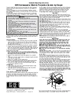
IC5201
24LC21AT/SN
IC5202
TC4053BF(EL)
IC5203
AD8185ARU
IC7222
IC7221
SN74AHCT1G14DBVR
SN74AHCT1G14DBVR
IC7141
BA7078AF-E2
IC5204
EL4332CS
IC1031
IC1041
IC1051
AD8057ART
AD8057ART
AD8057ART
IC101
AD8183ARU
IC5001
TC4052BF(EL)
IC3801
HIN232CB
IC3802
TC7SH00FU-
(TE85L)
IC3804
TWM7000-16020
IC3803
TWM7000-151020
IC2001
PC113B
INPUT-1
INPUT-2
INPUT-1
INPUT-3
I
2
C-SW
AIR MOUSE
CONTROLLER-2
AIR MOUSE
CONTROLLER-1
RS232C
DRIVER
Pb, Pr/Cb, Cr-SW
AUDIO-SW
SYNC-SW
SYNC-DET.
RGB-SW
MAIN
BOARD
"K8C"
MAIN
BOARD
"K8D"
MAIN
BOARD
"K8A"
DRIVE
BOARD
"K16S"
AUDIO-L
AUDIO-R
S-C
S-Y
Y/VIDEO
PB
PR
V-SYNC
H-SYNC
B
G
R
R
G
B
H-SYNC
Y-SYNC
Y/VIDEO
RB
PR
S-C
S-Y
AUDIO-R
AUDIO-L
MA8A-02
1
2
3
4
5
6
7
8
9
10
11
12
13
14
15
16
A
B
C
D
E
F
G
H
I
J
K
A
B
C
D
E
F
G
H
I
J
K
L
AV BOARD
A6
SCH_MA8P
Summary of Contents for LV-7545U
Page 2: ...CANON Power Projector LV 7545E D78 5231 SERVICE SMANUAL ...
Page 9: ......
Page 10: ...Part 1 General Information ...
Page 24: ......
Page 25: ...Part 2 Repair Information ...
Page 46: ...Part 3 Adjustment ...
Page 69: ...Part 4 Troubleshooting ...
Page 86: ...Part 4 Troubleshooting 4 17 BH3540 Volume Control IC1652 CXA2101AQ RGB Matrix IC4101 ...
Page 90: ...Part 4 Troubleshooting 4 21 LB1645 Motor Drive IC1601 LC863316 SUB CPU IC1851 ...
Page 91: ...Part 4 Troubleshooting 4 22 ML60851 USB I F IC9801 M62393 D A IC212 IC2381 ...
Page 93: ...Part 4 Troubleshooting 4 24 SII161ACT DVI I F IC8001 STR Z2156 Power Switching IC651 ...
Page 94: ...Part 4 Troubleshooting 4 25 TA1287 RGB YUV Converter IC4551 TB1274AF Video Decoder IC1101 ...
Page 95: ...Part 4 Troubleshooting 4 26 TDA7056 Audio Output IC1631 IC1632 ...
Page 96: ...Part 5 Parts Catalog ...
Page 97: ......
Page 113: ...Part 6 Electrical Diagrams ...
Page 130: ......