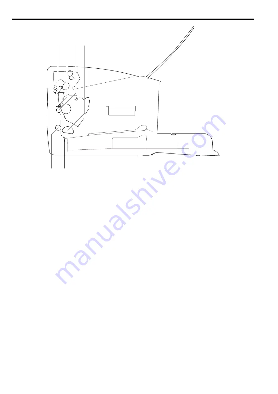
background image

Chapter 4  

4-2

F-4-1

T-4-1

Follow the procedure below for cleaning during servicing.
1) Fixing inlet guide

Clean it with a dry lint-free paper.

2) Static eliminator

Clean it with a dry lint-free paper.

3) Transfer roller

Basically, do not touch it with your hands or clean it. When cleaning is absolutely necessary, clean with a dry lint-free paper.
Take care not to touch the roller and let solvents or oils be removed.

4) Pickup roller

Clean it with a dry lint-free paper.

5) Separation pad

Clean the rubber part with a lint-free paper

6) Feeding roller

Clean it with a dry lint-free paper.

4.4.2 Cleaning Method

0025-1256

LBP6000 / LBP6000B

Cleaning at servicing

[1]

Fixing inlet guide

[2]

Static eliminator

[3]

Transfer roller

[4]

Pickup roller

[5]

Separation pad

[6]

Feeding roller

[1]

[3]

[4]

[6]

[5]

[2]

Summary of Contents for LBP3010 Series

Page 1: ...Sep 8 2010 Service Manual LBP6000 6018 3010 3100 3150 Series ...

Page 2: ......

Page 3: ... need arises In the event of major changes in the contents of this manual over a long or short period Canon will issue a new edition of this manual The following paragraph does not apply to any countries where such provisions are inconsistent with local law Trademarks The product names and company names used in this manual are the registered trademarks of the individual companies Copyright This ma...

Page 4: ...quiring care to avoid combustion fire Indicates an item prohibiting disassembly to avoid electric shocks or problems Indicates an item requiring disconnection of the power plug from the electric outlet Indicates an item intended to provide notes assisting the understanding of the topic in question Indicates an item of reference assisting the understanding of the topic in question Provides a descri...

Page 5: ...sed to indicate Low The voltage value how ever differs from circuit to circuit In addition the asterisk as in DRMD indicates that the DRMD signal goes on when 0 In practically all cases the internal mechanisms of a microprocessor cannot be checked in the field Therefore the operations of the microprocessors used in the machines are not discussed they are explained in terms of from sensors to the i...

Page 6: ......

Page 7: ...1 10 1 5 8 Safety of Toner 1 10 1 5 9 Handling the Laser Unit 1 11 1 5 10 Points to Note at Disassembly Assembly Work 1 11 Chapter 2 TECHNICAL REFERENCE 2 1 Functional Configuration 2 1 2 1 1 Outline 2 1 2 1 2 Outline 2 1 2 2 Basic Sequence 2 1 2 2 1 Basic Sequence of Operation 2 1 2 2 2 Power On Sequence 2 2 2 2 3 Basic Sequence of Operation 2 2 2 2 4 Power On Sequence 2 2 2 3 LASER EXPOSURE SYST...

Page 8: ...eloping Bias 2 20 2 4 2 8 Generating Transfer Bias 2 20 2 4 3 Toner Cartridge 2 20 2 4 3 1 Toner Level Detection 2 20 2 4 3 2 Toner Cartridge Absence Presence Detection 2 20 2 4 3 3 Toner Level Detection 2 22 2 4 3 4 Toner Cartridge Absence Presence Detection 2 22 2 5 PICKUP AND FEEDING SYSTEM 2 23 2 5 1 Overview Configuration 2 23 2 5 1 1 Overview 2 23 2 5 1 2 Overview 2 23 2 5 2 Detecting Jams 2...

Page 9: ... the Front Cover 3 6 3 1 5 4 Removing the Front Cover 3 6 3 1 6 Delivery Tray 3 7 3 1 6 1 Removing the Delivery Auxiliary Tray 3 7 3 1 7 Pickup Tray 3 7 3 1 7 1 Preparation for Removing the Pickup Tray Unit 3 7 3 1 7 2 Removing the Pickup Tray Unit 3 7 3 1 7 3 Before Removing the Pickup Tray Unit 3 8 3 1 7 4 Removing the Pickup Tray Unit 3 8 3 1 8 Drive Unit 3 9 3 1 8 1 Preparation for Removing th...

Page 10: ...paration for Removing the Pickup Unit 3 28 3 4 1 2 Removing the Pickup Unit 3 28 3 4 1 3 Before Removing the Pickup Unit 3 29 3 4 1 4 Removing the Pickup Unit 3 29 3 4 2 Cassette Pickup Roller 3 31 3 4 2 1 Removing the Pickup Roller 3 31 3 4 2 2 Removing the Pickup Roller 3 31 3 4 3 Cassette Pickup solenoid 3 32 3 4 3 1 Preparation for Removing the Pickup Solenoid 3 32 3 4 3 2 Removing the Pickup ...

Page 11: ...STMENT 5 2 5 2 1 Test Print 5 2 5 2 1 1 Test Print Function 5 2 5 2 2 Mechanical Adjustment 5 2 5 2 2 1 Nip width pressure from the pressure roller specifications 5 2 5 3 SERVICE TOOLS 5 3 5 3 1 Standard tools 5 3 5 3 2 Special Tool 5 3 5 3 3 List of solvent lubricant 5 3 5 4 ERROR CODE TABLE 5 4 5 4 1 Overview 5 4 5 4 2 Service Message 5 4 5 4 3 Overview 5 5 5 4 4 Service Message 5 5 5 5 Version ...

Page 12: ...Contents ...

Page 13: ...Chapter 1 PRODUCT DESCRIPTION ...

Page 14: ......

Page 15: ...oss Section 1 7 1 4 Using the Machine 1 8 1 4 1 Control Panel 1 8 1 4 2 Control Panel 1 8 1 5 Safety 1 8 1 5 1 Safety of Laser Light 1 8 1 5 2 CDRH Regulations 1 9 1 5 3 Safety of Toner 1 9 1 5 4 Handling the Laser Unit 1 9 1 5 5 Points to Note at Disassembly Assembly Work 1 10 1 5 6 Safety of Laser Light 1 10 1 5 7 CDRH Regulations 1 10 1 5 8 Safety of Toner 1 10 1 5 9 Handling the Laser Unit 1 1...

Page 16: ......

Page 17: ...tenance jam removal replacing the cartridge can be performed by ac cessing one point of the delivery tray MEMO 1 For this equipment the 16 ppm model and 14 ppm model are available according to the sales area The only difference between these models is the processing speed The following is the brand name for each product The letter B at the end of brand name in the following table indicates that th...

Page 18: ... the conventional gear drive method See MEMO 2 4 Improved Usability In this equipment the power switch is situated at the front of the host machine and maintenance jam removal replacing the cartridge can be performed by ac cessing one point of the delivery tray MEMO 1 The following is the brand name for each product The letter B at the end of brand name in the following table indicates that the ex...

Page 19: ...9 mm in width 127 to 355 6 mm in length Multi purpose paper size A4 B5 A5 LGL LTR Executive Envelope DL COM10 C5 Monarch user defined paper 76 2 to 215 9 mm in width 127 to 355 6 mm in length Pickup tray paper type plain paper 60 to 105 g m2 heavy paper 106 to 163 g m2 transparency label sheet postcard Multi purpose paper type plain paper 60 to 105 g m2 heavy paper 106 to 163 g m2 transparency lab...

Page 20: ...er 76 2 to 215 9 mm in width 188 to 355 6 mm in length Pickup tray paper type plain paper 60 to 105 g m2 heavy paper 106 to 163 g m2 transparency label sheet postcard envelope Pickup tray paper capacity Approx 150 sheets plain paper 64 g m2 Delivery tray stack Approx 100 sheets plain paper 64 g m2 Duplex method None Hard disk Standard none Option none Interface USB 2 0 Option none Memory Standard ...

Page 21: ...itch 2 Delivery auxiliary tray 3 Delivery tray 4 Manual feed tray paper guide 5 Manual feed tray 6 Tray cover 7 Pickup tray 8 Small size paper guide 9 Rear paper guide 10 Manual feed tray Paper guide 11 USB cover 12 USB connector 13 Power receptacle 1 2 3 10 4 5 6 7 8 9 12 13 11 ...

Page 22: ...3 1 Fixing unit 2 Pressure roller 3 Delivery roller 4 Fixing film unit 5 Laser scanner unit 6 Manual feed tray 7 Pickup tray 8 Photosensitive drum 9 Pickup roller 10 separation pad 11 Feed roller 12 Transfer roller 13 Toner cartridge 1 2 3 4 5 6 7 8 9 11 12 10 13 2 1 4 5 3 ...

Page 23: ...ay 4 Output Tray 5 Paper Guide 6 Rear Cover 7 USB Connector 8 Power Socket 1 Fixing unit 2 Pressure roller 3 Delivery roller 4 Fixing film unit 5 Laser scanner unit 6 Pickup tray 7 Photosensitive drum 8 Pickup roller 9 separation pad 10 Feed roller 11 Transfer roller 12 Toner cartridge 6 7 8 1 2 3 4 5 6 7 8 10 11 9 12 ...

Page 24: ...ting pickup of paper or jam removal restarts printing 1 4 2 Control Panel 0025 1124 LBP6000 LBP6000B F 1 7 1 Power lamp green Lighting Indicates that the power of the host machine is turned on Not lighting Indicates that the power of the host machine is not turned on 2 Paper lamp paper key red Lamp Flashing Indicates that there is no paper in the pickup source and print cannot be executed or paper...

Page 25: ...and after August 1 1976 and prohibit the sale of laser products without certification The following is a label used to certify compliance with the CDRH regulations and all laser products to be sold in the US must bear this label F 1 8 1 5 3 Safety of Toner 0019 1855 LBP3100 LBP3010B The machines toner is a non toxic material made up of plastic iron and small amounts of dye Toner on Clothing or Ski...

Page 26: ...ser is free of laser related hazards as long as the machine is being used for its intended purposes The following warnings are given to comply with Safety Principles EN60950 Laserstrahlen können für den menschlichen Körper gefährlich sein Aus diesem Grund ist das optische Lasersystem mit einem Schutzgehäuse und einer Außenab deckung dicht verschlossen und hat eine Struktur die keine Laserstrahlen ...

Page 27: ...eyes The unit cannot be adjusted in the field The following label is attached to the cover of the unit F 1 12 F 1 13 1 5 10 Points to Note at Disassembly Assembly Work 0025 1134 LBP6000 LBP6000B Be sure to ensure the following notes when performing disassembly assembly work 1 Be sure to disconnect the power plug for safety when performing disassembly assembly work 2 As for assembly procedure perfo...

Page 28: ......

Page 29: ...Chapter 2 TECHNICAL REFERENCE ...

Page 30: ......

Page 31: ...otor Fault Detection 2 9 2 4 IMAGE FORMATION SYSTEM 2 10 2 4 1 Overview Configuration 2 10 2 4 1 1 Overview 2 10 2 4 1 2 Print Process 2 10 2 4 1 3 Static Latent Image Formation Block 2 11 2 4 1 4 Development Block 2 12 2 4 1 5 Transfer Block 2 12 2 4 1 6 Fixing Block 2 13 2 4 1 7 Drum Cleaning Block 2 13 2 4 1 8 Overview 2 14 2 4 1 9 Print Process 2 14 2 4 1 10 Static Latent Image Formation Block...

Page 32: ...2 27 2 6 1 1 2 Low voltage power circuit 2 28 2 6 1 2 Protective Functions 2 29 2 6 1 2 1 Power protective function 2 29 2 6 1 2 2 Safety function 2 30 2 6 1 2 3 Power protective function 2 30 2 6 1 2 4 Safety function 2 30 2 7 ENGINE CONTROL SYSTEM 2 30 2 7 1 Main Controller 2 30 2 7 1 1 General description 2 30 2 7 1 2 General description 2 31 2 7 2 Engine Controller 2 31 2 7 2 1 General descrip...

Page 33: ...d externals auxiliary control system F 2 2 2 2 Basic Sequence 2 2 1 Basic Sequence of Operation 0019 4168 LBP3100 LBP3010B The engine controller controls the operation sequence The following table provides an outline of machine operation occurring from when the power switch is turned on to when printing ends and motors stop indicating the purposes of intervals and engine operation For details of v...

Page 34: ... keep the printer ready to print INTR initial rotation From the input of the print command from the main controller until the pick up solenoid is turned ON To stabilize the photosensitive drum sensitivity in preparation for printing Also to clean the transfer roller PRINT print From the end of the INTR period until the top of page sensor detects the trailing edge of paper To form image on the phot...

Page 35: ...roller rotates the Four faced mirror causing the Scanner motor to rotate 2 When the Scanner motor starts to rotate the Engine controller emits the laser forcibly using the Laser control signal causing the Engine controller to start rotation control for the Scanner motor 3 The Engine controller controls to keep a constant speed of rotation of the Scanner motor using the Scanner motor speed control ...

Page 36: ...er motor 3 The Engine controller controls to keep a constant speed of rotation of the Scanner motor using the Scanner motor speed control signal 4 After the rotation speed of the Scanner motor reaches its target the Main controller sends VIDEO signals to the Laser driver PCB 5 The Laser driver emits laser diode according to these signals 6 The laser beam passes through the collimator lens and the ...

Page 37: ...details of control procedure 1 The engine controller controls the laser control signal during unblanking to emit the laser diode LD forcibly 2 The BD PCB exists on the scanning route of the laser beam which is sent to the BD PCB 3 The BD PCB detects this laser beam creates BD input signal BDI and sends it to the engine controller 4 The engine controller creates horizontal sync signals BD based on ...

Page 38: ... well as the video signal VD0 VD0 for image formation The laser driver IC executes laser control according to the combination of the CNT0 CNT1 signals The following is the combination of the laser control signal CNT0 CNT1 T 2 4 2 3 2 4 Horizontal Sync Control 0025 1142 LBP6000 LBP6000B This is the control to adjust the writing position in the image horizontal direction Operation mode CNT0 CNT1 Rem...

Page 39: ...rol signal enters LD forced OFF mode the LD is forcibly turned off The laser driver saves the adjusted laser intensity to the capacitor C1 2 3 3 2 Auto Power Control APC 0025 1143 LBP6000 LBP6000B This is the control to emit a constant level of laser diode There are two types of APC initial APC note 1 and line space APC note 2 The laser driver executes the same procedure for both controls The foll...

Page 40: ...into either of the following status the engine controller judges it as a fault in the laser scanner unit system and notices the status of fault to the main controller The operations of the host machine are stopped 1 Fault in BD input At startup of the scanner BDI signal cannot be detected within 0 1 sec from the completion of forced acceleration of the scanner motor 2 Fault in startup During activ...

Page 41: ...25 1149 LBP6000 LBP6000B This is the detection of faults in the laser scanner unit When the laser unit scanner unit falls into either of the following status the engine controller judges it as a fault in the laser scanner unit system and notices the status of fault to the main controller The operations of the host machine are stopped 1 Fault in BD input At startup of the scanner BDI signal cannot ...

Page 42: ...00 LBP3010B This explains the basic process of the operations that a printer executes for image formation The print process of this equipment is divided largely into 5 blocks 7 steps Toner images are formed on papers by executing the steps of each block in order The following are the blocks of print process and the steps 1 Static latent image formation block Step 1 Primary charging Step2 Laser bea...

Page 43: ... the primary charging roller directly to the photosensitive drum DC bias is applied to the primary charging roller to maintain an even potential on the surface of the photosensitive drum F 2 12 Step 2 Laser beam exposure In this step static latent images are formed on the photosensitive drum with laser beam When laser beams are scanned on the photosensitive drum negatively charged bright areas los...

Page 44: ... laser beam has higher potential than the developing cylinder the potential difference between the drum surface and the cylinder enables the toner to jump on the drum surface and makes them visible images AC bias superimposed with the development DC negative bias is applied to the developing cylinder F 2 14 2 4 1 5 Transfer Block 0019 5408 LBP3100 LBP3010B This block is comprised of two steps it t...

Page 45: ...to fix toner images to the papers Step 6 Fixing This step employs on demand fixing that fixes toner images transferred to papers on the papers F 2 17 2 4 1 7 Drum Cleaning Block 0019 5437 LBP3100 LBP3010B The drum cleaning block removes the toner remained on the photosensitive drum Step 7 Drum cleaning In this step toner remained on the photosensitive drum is removed The cleaning blade scrapes the...

Page 46: ...tions of image formation F 2 19 2 4 1 9 Print Process 0025 1153 LBP6000 LBP6000B This explains the basic process of the operations that a printer executes for image formation The print process of this equipment is divided largely into 5 blocks 7 steps Toner images are formed on papers by executing the steps of each block in order Cleaning blade Photosencitive drum Cleaner container Fixing unit Ton...

Page 47: ...exposed The images on the drum with negative charge are called static latent images because human eyes cannot detect them F 2 21 Step 1 Primary charging For preparation of latent image formation the surface of photosensitive drum is charged with even negative potential In this primary charging the charge is applied from the primary charging roller directly to the photosensitive drum DC bias is app...

Page 48: ...evelops the images The toner developer used for this equipment is a one component toner that comprises magnetic body and resin etc Step 3 Development Toner is affixed to static latent images on the surface of the photosensitive drum The toner is charged negatively by friction between the developing cylinder and the surface of the developing blade An area on the photosensitive drum exposed with las...

Page 49: ...e bias is applied to the static eliminator according to the elasticity of papers to separate the papers from the photosensitive drum The static eliminator is used to stabilize the paper feed system prevention of toner stray that appears as polka dots on print images in a low temperature low humidity envi ronment and neutralizes the electric charge at the back of papers F 2 26 2 4 1 13 Fixing Block...

Page 50: ...m is cleaned F 2 28 2 4 2 High Voltage Control 2 4 2 1 Overview 0019 5443 LBP3100 LBP3010B This circuit is comprised of the circuits that apply biases to the primary charging roller developing cylinder transfer roller and the fixing control circuit The CPU of the engine controller controls the high voltage power supply circuit to generate these biases The fixing control circuit executes heater con...

Page 51: ...e high voltage power supply circuit The DC positive bias is output at the time of toner transfer and the DC negative bias at the time of cleaning the photosensitive drum The high voltage power supply circuit applies the generated transfer bias to the transfer roller according to each print sequence Each print sequence is described below Cleaning bias The bias to move clean the toner attached to th...

Page 52: ...to papers There are two types of bias DC positive bias and DC negative bias and generated by the transfer high voltage generating circuit in the high voltage power supply circuit The DC positive bias is output at the time of toner transfer and the DC negative bias at the time of cleaning the photosensitive drum The high voltage power supply circuit applies the generated transfer bias to the transf...

Page 53: ...eing H it is judged that the Toner cartridge is present F 2 31 The leading edge sensor performs both this detection and paper feed detection Therefore the engine controller cannot make a judgment of Toner cartridge absent or jam occurrence when jam occurs The engine controller judges this case as Toner cartridge absent and notices it to the main controller If jam occurs when Toner cartridge absent...

Page 54: ...PS801 When the output result of PS801 is L it is judged that the Toner cartridge is absent If being H it is judged that the Toner cartridge is present F 2 32 The leading edge sensor performs both this detection and paper feed detection Therefore the engine controller cannot make a judgment of Toner cartridge absent or jam occurrence when jam occurs The engine controller judges this case as Toner c...

Page 55: ... sensor PS702 Fixing delivery sensor PS801 Paper leading edge sensor M1 Main motor SL1 Pickup solenoid 2 5 1 2 Overview 0025 1168 LBP6000 LBP6000B The pickup feeding system executes pickup and feeding of papers and is composed of the main motor solenoid and rollers In this equipment pickup from the pickup tray and manual feed tray is available There is only a face down delivery Papers set on the p...

Page 56: ...rview 0019 5975 LBP3100 LBP3010B The following sensors are installed to detect absence presence of papers and whether papers are correctly fed Paper width sensor PS701 Fixing delivery sensor PS702 Paper leading edge sensor PS801 Pressure roller Delivery roller Pickup tray Fixing film Photosensitive drum Transfer roller Pickup roller Separation pad PS801 PS701 PS702 SL1 M1 Engine controller Main co...

Page 57: ...BP6000 LBP6000B The following sensors are installed to detect absence presence of papers and whether papers are correctly fed Paper width sensor PS701 Fixing delivery sensor PS702 Paper leading edge sensor PS801 F 2 36 Whether jam occurs or not is judged according to whether a paper is absent present on the sensor at the check timing that has been stored in the CPU of the engine controller When th...

Page 58: ... PS801 2 5 2 3 4 Delivery Stationary Jam 0025 1172 LBP6000 LBP6000B If 0 9 sec passes after the paper leading edge sensor PS801 detects the paper absent and in addition the fixing delivery sensor PS702 cannot detect the paper within approx 0 4 sec after that CPU determines the delivery stationary JAM 2 5 2 4 Other Jams 2 5 2 4 1 Fixing Take up Jam 0019 7895 LBP3100 LBP3010B CPU detects fixing take...

Page 59: ...sensor PS801 detects the paper CPU determines that there is the residual paper at startup and informs it to the main controller then stops a printer After that when the auto delivery is instructed by the main controller CPU drives the motor and delivers the residual paper to the outside of the machine 2 6 EXTERNAL AND CONTROLS SYSTEM 2 6 1 Power Supply 2 6 1 1 Power Supply 2 6 1 1 1 Low voltage po...

Page 60: ...ed for the host machine in this circuit The following is the block diagram of low voltage circuit and the DC power supply route FU101 FREQSNS 24V 24V 24V 5V 3 3V 3 3V SW502 3 3V 3 3VOFF PWSV 24VOFF FU201 110 127V model only Engine controller Low voltage power supply High voltage power supply Fixing control Noise filter Noise filter Frequency detection circuit 220 240V model only 24V generation cir...

Page 61: ...ON the switch again see note 1 Also the circuit carries the 2 fuses FU101 FU102 as a preventive function see note 2 The fuses blow to block the power supply when overcurrent occurs in AC line 1 When restoring the low voltage power after protective function is activated leave it for 2 minutes or more from turning off the switch or plugging out before turning ON FU101 FREQSNS 24V 24V 24V 5V 3 3V 3 3...

Page 62: ...stopping 24V of fixing assembly and the high voltage power unit to avoid users and engineers from getting burned or electric shock When the cartridge door is opened the interlock switch SW501 is turned off and 24V supplied to fixing assembly and the high voltage power unit is shut Engine controller CPU determines the door open when each interlock switch is turned OFF 2 7 ENGINE CONTROL SYSTEM 2 7 ...

Page 63: ...and sends the printer status to the external devices F 2 40 2 7 2 Engine Controller 2 7 2 1 General description 0019 7722 LBP3100 LBP3010B Engine controller is the circuit to control the operation sequence of the host machine and it is controlled by the CPU inside the engine controller When the power is turned ON and DC power is supplied through the low voltage power inside engine controller CPU s...

Page 64: ...32 F 2 41 AC input Fixing unit Motor Transfer roller High voltage power supply Low voltage power supply Laser scanner unit Solenoid Main controller Toner Cartridge Sensor CPU Switch Engine controller Fixing control ...

Page 65: ...r inside engine controller CPU starts the printer operation control Then CPU drives the loads such as laser diode motors and solenoids etc according to the image data that is input by the main controller when status becomes stand by mode The following is the block diagram of this circuit F 2 42 AC input Fixing unit Motor Transfer roller High voltage power supply Low voltage power supply Laser scan...

Page 66: ...roller then the paper is delivered from the fixing assembly The paper is detected by the delivery sensor PS701 and the paper width sensor PS702 and then delivered to the delivery tray by the delivery roller F 2 43 T 2 5 2 8 1 2 Main Parts of Fixing Unit 0019 7080 LBP3100 LBP3010B Main parts configuration and its purposes inside the fixing assembly are described below F 2 44 T 2 6 Name 1 Fixing fil...

Page 67: ...76 LBP6000 LBP6000B Main parts configuration and its purposes inside the fixing assembly are described below 5 Fixing film unit 6 Fixing assembly Fixing heater This fixing assembly is equipped with 1 heater Fixing heater H1 For heating the fixing film ceramic heater Thermistor This fixing assembly is equipped with 1 thermistor Main thermistor TH1 For controlling the fixing heater temperature conta...

Page 68: ...heater temperature within the target values The following is the block diagram of this control Name 1 Pressure roller 2 Temperature fuse 3 Thermistor 4 Fixing heater 5 Fixing film unit 6 Fixing assembly Fixing heater This fixing assembly is equipped with 1 heater Fixing heater H1 For heating the fixing film ceramic heater Thermistor This fixing assembly is equipped with 1 thermistor Main thermisto...

Page 69: ...ency 600dpi 150 to 160 deg C 400dpi 165 to 180 deg C Postcard postcard H 600dpi 188 deg C 400dpi 188 deg C Envelope 600dpi 130 to 150 deg C Labels 600dpi 130 to 150 deg C Resolution Settings This machine has 2 types of resolution settings 600 x 600 dpi 600 x 400dpi This setting can be changed by whether or not ticking the item on finish settings Finishing Process Option Use output adjustment mode ...

Page 70: ...s see the note below etc on a driver The following is the relation list of the fixing target temperature and the driver settings T 2 10 Settings on Printer Driver Target fixing temperature Paper type settings Sub scanning direction Plain paper 600dpi 150 to 165 deg C 400dpi 170 to 190 deg C Plain paper L 600dpi 140 to 155 deg C 400dpi 160 to 180 deg C Thick paper 600dpi 170 deg C Thick paper H 600...

Page 71: ... at printing after the thermistor temperature reaches 50 deg C After heater ON when the thermistor detects the temperature of 55 deg C or below at sheet interval or in cleaning mode after thermistor temperature reaches 50 deg C 3 Overheat error When the thermistor detects the temperature of 220 deg C or over 30 times consecutively 4 Frequency detection circuit error 200 240V series only When it ca...

Page 72: ...narrow width and to prevent the fixing heater unit from overheating at high volume continuous print ing This control extends the interval between heater on and prevents the edge of the roller of fixing assembly and the delivery unit from overheating This control has the following 3 modes and the operation sequence differs depending on each modes Mode 1 sequence For prevention of temperature increa...

Page 73: ...taneously control the target temperature of the fixing assembly according to the temperature in the following table F 2 50 T 2 12 Mode 2 sequence For prevention of temperature increase in the edge Condition paper length is 264mm or longer while paper width is 190mm or shorter Operation print speed drops to 3ppm from the 2nd sheet of continuous print Simultaneously control the target temperature of...

Page 74: ......

Page 75: ...Chapter 3 DISASSEMBLY AND ASSEMBLY ...

Page 76: ......

Page 77: ...1 7 1 Preparation for Removing the Pickup Tray Unit 3 7 3 1 7 2 Removing the Pickup Tray Unit 3 7 3 1 7 3 Before Removing the Pickup Tray Unit 3 8 3 1 7 4 Removing the Pickup Tray Unit 3 8 3 1 8 Drive Unit 3 9 3 1 8 1 Preparation for Removing the Drive Belt 3 9 3 1 8 2 Removing the Drive Belt 3 9 3 1 8 3 Before Removing the Drive Belt 3 10 3 1 8 4 Removing the Drive Belt 3 10 3 1 9 Main Drive Unit...

Page 78: ... 3 28 3 4 1 2 Removing the Pickup Unit 3 28 3 4 1 3 Before Removing the Pickup Unit 3 29 3 4 1 4 Removing the Pickup Unit 3 29 3 4 2 Cassette Pickup Roller 3 31 3 4 2 1 Removing the Pickup Roller 3 31 3 4 2 2 Removing the Pickup Roller 3 31 3 4 3 Cassette Pickup solenoid 3 32 3 4 3 1 Preparation for Removing the Pickup Solenoid 3 32 3 4 3 2 Removing the Pickup Solenoid 3 32 3 4 3 3 Before Removing...

Page 79: ... 3 Before Remove the Rear Cover 0025 1204 LBP6000 LBP6000B 1 Remove the Upper Cover page 3 5 Reference Removing the Upper Cover 2 Remove the Left Cover page 3 3 Reference Removing the Left Cov er 3 Remove the Right Cover page 3 2 Reference Removing the Right Cover 3 1 1 4 Removing the Rear Cover 0025 1205 LBP6000 LBP6000B 1 Remove the Rear Cover 1 1 Screw 2 2 Hooks 3 F 3 2 3 1 2 Right Cover 3 1 2 ...

Page 80: ...ng the Right Cover 0025 1208 LBP6000 LBP6000B 1 Remove the screw 1 and release the 3 claws 2 2 While releasing the 3 hooks 3 remove the Right Cover 4 in the direc tion of the arrow F 3 4 3 1 3 Left Cover 3 1 3 1 Preparation for Removing the Left Cover 0019 2080 LBP3100 LBP3010B 1 Removing the Upper Cover page 3 3 Reference Removing the Upper Cover 3 1 3 2 Removing the Left Cover 0019 2081 LBP3100 ...

Page 81: ... 3 1 3 4 Removing the Left Cover 0025 1210 LBP6000 LBP6000B 1 Remove the screw 1 and release the 3 claws 2 2 While releasing the 3 hooks 3 remove the Left Cover 4 in the direction of the arrow F 3 6 3 1 4 Upper Cover 3 1 4 1 Removing the Upper Cover 0019 2140 LBP3100 LBP3010B 1 Open the delivery auxiliary tray 1 and delivery tray 2 MEMO The following shows the 3 claws 1 and 3 hooks 2 of the Left C...

Page 82: ...rection 4 While releasing the 3 claws 4 remove the upper cover in the arrow B direction F 3 8 2 1 Points to note at installation Attach the left and right fixing pressure arms 2 to the left and right holes 1 of the delivery tray Attach the cartridge lock arm 4 to the arm unit 3 on the delivery tray 1 A B 2 2 4 3 ...

Page 83: ... and the Delivery Tray 2 F 3 9 2 Remove the Cartridge Arm 1 3 Release the 2 claws 2 of the Upper Cover F 3 10 4 Remove the Upper Cover 1 6 Claws 2 3 Hooks 3 F 3 11 MEMO The following shows the 2 claws 1 at rear side of the Upper Cover Unit 6 claws 2 at the sides and 3 hooks 3 1 2 1 3 2 4 1 2 3 2 1 2 1 2 1 2 2 3 ...

Page 84: ...0025 1212 LBP6000 LBP6000B 1 Remove the Upper Cover page 3 5 Reference Removing the Upper Cover 2 Remove the Left Cover page 3 3 Reference Removing the Left Cov er 3 Remove the Right Cover page 3 2 Reference Removing the Right Cover 3 1 5 4 Removing the Front Cover 0025 1213 LBP6000 LBP6000B Points to Note at Installation Be sure to fit the 2 Fixing Pressure Arms Right and Left 2 into the 2 holes ...

Page 85: ...Cover 2 Removing the Left Cover page 3 2 Reference Removing the Left Cov er 3 Removing the Right Cover page 3 2 Reference Removing the Right Cover 4 Removing the Front Cover page 3 6 Reference Removing the Front Cover 5 Removing the Rear Cover page 3 1 Reference Removing the Rear Cover 6 Removing the Separation Pad page 3 34 Reference Removing the Sep aration Pad 3 1 7 2 Removing the Pickup Tray U...

Page 86: ... Reference Removing the Front Cover 5 Remove the Separation Pad page 3 34 Reference Removing the Sep aration Pad 3 1 7 4 Removing the Pickup Tray Unit 0025 1217 LBP6000 LBP6000B 1 Remove the 4 screws 1 and turn the machine in the direction of the ar row F 3 18 2 Remove the Pickup Tray Unit 3 4 Screws 1 4 Hooks 2 When attaching the pickup tray to the host machine put the pickup tray 2 onto the pick...

Page 87: ...the Front Cover 3 1 8 2 Removing the Drive Belt 0019 2623 LBP3100 LBP3010B 1 Remove the tension unit 1 1 screw 2 F 3 20 2 Remove the drive cover 1 4 screws 2 F 3 21 3 Remove the 2 gears 1 Be sure to place the springs 1 between A and B parts of the Pickup Tray Unit when assembling When installing the Pickup Tray Unit to the machine be sure to put the Pickup Tray 2 onto the Pickup Roller 1 1 2 3 1 A...

Page 88: ...BP6000 LBP6000B 1 Remove the Tension Unit 1 1 Screw 2 F 3 24 2 Remove the Drive Cover 1 4 Screws 2 Points to note at installation When assembling the drive gears follow the order as below 1 Primary speed down pulley 2 Timing belt 3 Fixing ratchet gear 4 Fixing gear 5 Cartridge gear 6 Coupling gear 7 Delivery speed down W gear 8 Compression spring 9 Compression spring When attaching the drive gear ...

Page 89: ... the order shown below 1 2 3 1 1 2 2 2 1 1 1 1 Primary Deceleration Pully 2 Timing Belt 3 Fixing Ratchet Gear 4 Fixing Transmission Gear 5 Cartridge Transmission Gear 6 Coupling Gear 7 Feed Deceleration Gear 8 Compression Spring 9 Compression Spring When installing the Drive Cover be sure to align the 7 Shaft Holes 1 with the Drive Cover 2 1 2 3 6 7 9 8 4 5 1 2 1 ...

Page 90: ...t Cov er 3 Removing the Right Cover page 3 2 Referense Removing the Right Cover 4 Removing the Front Cover page 3 6 Referense Removing the Front Cover 3 1 9 2 Removing the Main Motor 0019 2416 LBP3100 LBP3010B 1 Remove the scanner sub cover 1 1 screw 2 F 3 28 2 Remove the scanner cover 1 3 screws 2 F 3 29 3 Remove the tension unit 1 1 screw 2 F 3 30 4 Disconnect the connecter 1 F 3 31 5 Remove the...

Page 91: ... Left Cover page 3 3 Reference Removing the Left Cov er 3 Remove the Right Cover page 3 2 Reference Removing the Right Cover 4 Remove the Front Cover page 3 6 Reference Removing the Front Cover 3 1 9 4 Removing the Main Motor 0025 1224 LBP6000 LBP6000B 1 Remove the Scanner Sub Cover 1 1 Screw 2 F 3 35 2 Remove the Scanner Cover 1 3 Screws 2 1 1 2 2 1 2 3 3 4 Points to note at installation When att...

Page 92: ...w 2 F 3 37 4 Disconnect the connector 1 F 3 38 5 Remove the Motor Driver PCB 1 3 Claws 2 F 3 39 6 Free the Motor Harness 2 from the Harness Guide 1 7 Remove the Motor Guide 3 1 Screw 4 F 3 40 8 Remove the Main Motor 1 2 Screws 2 1 2 2 1 2 1 1 1 2 2 1 2 3 3 4 ...

Page 93: ...ver 6 Removing the Main Controller PCB page 3 17 Referense Removing the Main Controller PCB 3 1 10 2 Removing the Engine Controller PCB 0019 3453 LBP3100 LBP3010B 1 Remove the inner rear cover 1 1 screw 2 F 3 42 2 Remove the terminal 1 and free the harness 3 from the harness guide 2 F 3 43 3 Remove the boss 1 and remove the protective cover 2 F 3 44 4 Disconnect the 2 flat cables 1 and the 5 conne...

Page 94: ... 6 Remove the Main Controller PCB page 3 17 Reference Removing the Main Controller PCB 3 1 10 4 Removing the Engine Controller PCB 0025 1226 LBP6000 LBP6000B 1 Remove the Main Controller PCB Installation Plate 1 1 Screw with washer 2 2 Screws TP 3 F 3 46 2 Remove the terminal 1 and free the harness 3 from the Harness Guide 2 F 3 47 3 Remove the boss 1 and remove the Protection Cover 2 F 3 48 4 Dis...

Page 95: ...e 2 1 screw w washer 3 2 screws TP 4 F 3 51 2 Remove the guide 1 in the arrow A direction 1 claw 2 3 Remove the 4 screws 3 and remove the main controller PCB 4 in the arrow B direction F 3 52 3 1 11 3 Before Remove the Main Controller PCB 0025 1227 LBP6000 LBP6000B 1 Remove the Upper Cover page 3 5 Reference Removing the Upper Cover 2 Remove the Left Cover page 3 3 Reference Removing the Left Cov ...

Page 96: ...over page 3 1 Reference Removing the Rear Cover 6 Removing the Separation Pad page 3 34 Reference Removing the Sep aration Pad 7 Removing the Pickup Tray Unit page 3 7 Reference Removing the Pickup Tray Unit 3 1 12 2 Removing the Memory Contact Unit 0019 4854 LBP3100 LBP3010B 1 Remove the scanner sub cover 1 1 screw 2 F 3 54 2 Remove the scanner cover 1 3 screws 2 F 3 55 3 Disconnect the connecter...

Page 97: ...host machine 1 in the direction of the arrow F 3 60 8 Free the harness 2 from the harness guide 1 F 3 61 9 Lift the memory contact unit 1 in the direction of the arrow and release the lower claw 2 F 3 62 10 Remove the memory contact unit 1 2 hooks 2 1 screw 3 F 3 63 1 1 2 1 1 2 1 2 2 3 1 ...

Page 98: ...34 Reference Removing the Sep aration Pad 7 Remove the Pickup Tray Unit page 3 8 Reference Removing the Pickup Tray Unit 3 1 12 4 Removing the Memory Contact Unit 0025 1230 LBP6000 LBP6000B 1 Remove the Scanner Sub Cover 1 1 Screw 2 F 3 64 2 Remove the Scanner Cover 1 3 Screws 2 F 3 65 3 Disconnect the connector 1 and take it out from the hole 2 on the Side Plate F 3 66 4 Disconnect the harness 1 ...

Page 99: ... Paper Leading Edge Sensor 0019 4445 LBP3100 LBP3010B 1 Removing the Upper Cover page 3 3 Reference Removing the Upper Cover 2 Removing the Left Cover page 3 2 Reference Removing the Left Cov er 3 Removing the Right Cover page 3 2 Reference Removing the Right Cover 4 Removing the Rear Cover page 3 1 Reference Removing the Rear Cover 5 Removing the Main Controller PCB page 3 17 Reference Removing t...

Page 100: ...BP3010B 1 Remove the inner rear cover 1 1 screw 2 F 3 74 2 Remove the terminal 1 and free the harness 3 from the harness guide 2 F 3 75 3 Disconnect the 4 connecters 1 and free the harness 3 from the harness guide 2 4 Remove the paper leading edge sensor 4 F 3 76 1 2 1 2 3 1 1 2 3 4 ...

Page 101: ...rom the Harness Guide 2 3 Remove the Paper Leading Edge Sensor 4 F 3 78 3 1 14 Sensor Boade 3 1 14 1 Preparation for Removing the Sensor PCB 0019 4218 LBP3100 LBP3010B 1 Removing the Upper Cover page 3 3 Reference Removing the Upper Cover 2 Removing the Left Cover page 3 2 Reference Removing the Left Cov er 3 Removing the Right Cover page 3 2 Reference Removing the Right Cover 4 Removing the Rear ...

Page 102: ...rew 2 F 3 79 2 Remove the terminal 1 and free the harness 3 from the harness guide 2 F 3 80 3 Remove the 4 connecters 1 and free the harness 3 from the harness guide 2 4 Disconnect the connecter 4 and remove the sensor PCB 5 F 3 81 1 2 1 2 3 1 1 2 5 4 3 ...

Page 103: ...ors 1 and free the harness 3 from the Harness Guide 2 3 Disconnect the connector 4 and remove the Sensor PCB 5 F 3 83 3 2 LASER EXPOSURE SYSTEM 3 2 1 Laser Scanner Unit 3 2 1 1 Preparation for Removing the Laser Scanner Unit 0019 2196 LBP3100 LBP3010B 1 Removing the Upper Cover page 3 3 Reference Removing the Upper Cover 2 Removing the Left Cover page 3 2 Reference Removing the Left Cov er 3 Remov...

Page 104: ...nce Removing the Upper Cover 2 Remove the Left Cover page 3 3 Reference Removing the Left Cov er 3 Remove the Right Cover page 3 2 Reference Removing the Right Cover 4 Remove the Front Cover page 3 6 Reference Removing the Front Cover 3 2 1 4 Removing the Laser Scanner Unit 0025 1238 LBP6000 LBP6000B 1 Remove the Scanner Sub Cover 1 1 Screw 2 Do not disassemble the laser scanner unit because it ne...

Page 105: ...B 1 Open the delivery auxiliary tray 1 and the delivery tray 2 2 While pushing the 2 claws 3 remove the transfer roller 4 F 3 90 Be sure not to disassemble the Laser Scanner Unit because it requires adjustment 1 2 1 2 2 1 2 3 4 Points to Note at Installation When installing the Laser Scanner Cover 1 be sure to put the Shutter Open Close Lever 2 through the hole 3 on the Scanner Cover Avoid contact...

Page 106: ...Removing the Left Cover page 3 2 Reference Removing the Left Cov er 3 Removing the Right Cover page 3 2 Reference Removing the Right Cover 4 Removing the Rear Cover page 3 1 Reference Removing the Rear Cover 5 Removing the Main Controller PCB page 3 17 Reference Removing the Main Controller PCB 3 4 1 2 Removing the Pickup Unit 0019 4145 LBP3100 LBP3010B 1 Remove the inner rear cover 1 1 screw 2 F ...

Page 107: ...g the Right Cover 4 Remove the Rear Cover page 3 1 Reference Removing the Rear Cov er 5 Remove the Main Controller PCB page 3 17 Reference Removing the Main Controller PCB 3 4 1 4 Removing the Pickup Unit 0025 1241 LBP6000 LBP6000B 1 Remove the Shaft Retainer 1 1 2 3 1 1 2 3 2 2 1 Points to note at installation When installing the pickup unit 1 make sure that the contact spring 2 contacts with A p...

Page 108: ...ckup Unit 1 6 Screws 2 F 3 100 1 1 1 2 3 Points to Note at Installation When installing the Pickup Unit 1 be sure to make the Contact Spring 2 comes in contact with A part Be sure to make the grounding contact point 3 comes in contact with B part Points to Note at Installation When installing the terminal 1 be sure that the Contact Spring 2 is in contact with it as shown below 1 1 2 3 2 2 1 2 A B ...

Page 109: ...ght and left claws 3 and remove the pickup roller 4 F 3 101 3 4 2 2 Removing the Pickup Roller 0025 1242 LBP6000 LBP6000B Avoid contact with the transfer roller when removing the pickup roller 2 1 1 When disassembling assembling be sure not to touch the surface of the Pickup Roller When disassembling assembling the Pickup Roller be sure not to touch the Transfer Roller 1 1 2 3 4 ...

Page 110: ...the Left Cov er 3 Removing the Right Cover page 3 2 Reference Removing the Right Cover 4 Removing the Rear Cover page 3 1 Reference Removing the Rear Cover 5 Removing the Main Controller PCB page 3 17 Reference Removing the Main Controller PCB 3 4 3 2 Removing the Pickup Solenoid 0019 4448 LBP3100 LBP3010B 1 Remove the inner rear cover 1 1 screw 2 F 3 103 2 Remove the terminal 1 and free the harne...

Page 111: ...17 Reference Removing the Main Controller PCB 3 4 3 4 Removing the Pickup Solenoid 0025 1244 LBP6000 LBP6000B 1 Remove the terminal 1 and free the harness 3 from the Harness Guide 2 F 3 106 2 Disconnect the 4 connectors 1 3 Free the harness 3 from the Harness Guide 2 4 Remove the screw 5 to remove the Pickup Solenoid 4 F 3 107 Points to note at installation When attaching the terminal 1 make sure ...

Page 112: ...Cover 2 Removing the Left Cover page 3 2 Reference Removing the Left Cov er 3 Removing the Right Cover page 3 2 Reference Removing the Right Cover 4 Removing the Rear Cover page 3 1 Reference Removing the Rear Cover 5 Removing the Main Controller PCB page 3 17 Reference Removing the Main Controller PCB 3 5 1 2 Removing the Fixing Unit 0019 4276 LBP3100 LBP3010B 1 Remove the inner rear cover 1 1 sc...

Page 113: ...Chapter 3 3 35 F 3 112 6 Remove the harness holder 1 1 screw 2 F 3 113 7 Remove the fixing unit 1 3 screws 2 F 3 114 4 5 2 3 1 1 1 2 2 2 1 ...

Page 114: ...CB 3 5 1 4 Removing the Fixing Assembly 0025 1248 LBP6000 LBP6000B 1 Remove the terminal 1 and free the harness 3 from the Harness Guide 2 F 3 115 2 Disconnect the 4 connectors 1 3 Free the harness 3 from the Harness Guide 2 4 Free the Fixing Harness 5 from the Harness Holder 4 F 3 116 5 Remove the Harness Holder 1 1 Claw 2 Points to note at installation When attaching the fixing harness wind the ...

Page 115: ...the Upper Cover 2 Removing the Left Cover page 3 2 Reference Removing the Left Cov er Points to Note at Installation When attaching the Fixing Harness in place be sure to wind the Fixing Harness 2 around the protrusion 1 of the Harness Holder and secure it with the Harness Guide 3 1 2 2 2 1 Points to Note at Installation When installing the terminal 1 be sure that the Contact Spring 2 is in contac...

Page 116: ...pressure plates 1 2 springs 2 2 pressure arms 3 F 3 122 5 Remove the fixing film unit 1 F 3 123 3 5 2 3 Before Removing the Fixing Film Unit 0025 1249 LBP6000 LBP6000B 1 Remove the Upper Cover page 3 5 Reference Removing the Upper Cover 2 Remove the Left Cover page 3 3 Reference Removing the Left Cov er 3 Remove the Right Cover page 3 2 Reference Removing the Right Cover 4 Remove the Rear Cover pa...

Page 117: ...er page 3 2 Reference Removing the Left Cov er 3 Removing the Right Cover page 3 2 Reference Removing the Right Cover 4 Removing the Rear Cover page 3 1 Reference Removing the Rear Cover 5 Removing the Main Controller PCB page 3 17 Reference Removing the Main Controller PCB 6 Removing the Fixing Assembly page 3 34 Reference Removing the Fixing Assembly 7 Removing the Fixing Film Unit page 3 38 Ref...

Page 118: ...ver 4 Remove the Rear Cover page 3 1 Reference Removing the Rear Cov er 5 Remove the Main Controller PCB page 3 17 Reference Removing the Main Controller PCB 6 Remove the Fixing Assembly page 3 36 Reference Removing the Fixing Assembly 7 Remove the Fixing Film Unit page 3 38 Reference Removing the Fix ing Film Unit 3 5 3 4 Removing the Fixing Pressure Roller 0025 1253 LBP6000 LBP6000B 1 Remove the...

Page 119: ...Chapter 4 MAINTENANCE AND INSPECTION ...

Page 120: ......

Page 121: ...eplaced Parts 4 1 4 1 2 Periodically Replaced Parts 4 1 4 2 Consumables 4 1 4 2 1 Consumables 4 1 4 2 2 Consumables 4 1 4 3 Periodical Service 4 1 4 3 1 Scheduled Servicing 4 1 4 3 2 Scheduled Servicing 4 1 4 4 Cleaning 4 1 4 4 1 Cleaning Method 4 1 4 4 2 Cleaning Method 4 2 ...

Page 122: ......

Page 123: ...bles 0019 6365 LBP3100 LBP3010B There is no consumable with this machine 4 2 2 Consumables 0025 1254 LBP6000 LBP6000B There is no consumable with this machine 4 3 Periodical Service 4 3 1 Scheduled Servicing 0019 6366 LBP3100 LBP3010B There is no portion that requires schedule servicing in this equipment 4 3 2 Scheduled Servicing 0025 1255 LBP6000 LBP6000B There is no portion that requires schedul...

Page 124: ...s absolutely necessary clean with a dry lint free paper Take care not to touch the roller and let solvents or oils be removed 4 Pickup roller Clean it with a dry lint free paper 5 Separation pad Clean the rubber part with a lint free paper 6 Feeding roller Clean it with a dry lint free paper 4 4 2 Cleaning Method 0025 1256 LBP6000 LBP6000B Cleaning at servicing 1 Fixing inlet guide 2 Static elimin...

Page 125: ...ur hands or clean it When cleaning is absolutely necessary clean with a dry lint free paper Take care not to touch the roller and let solvents or oils be removed 4 Pickup roller Clean it with a dry lint free paper 5 Separation pad Clean the rubber part with a lint free paper 6 Feeding roller Clean it with a dry lint free paper 1 Fixing inlet guide 2 Static eliminator 3 Transfer roller 4 Pickup rol...

Page 126: ......

Page 127: ...Chapter 5 TROUBLESHOOTING ...

Page 128: ......

Page 129: ...JUSTMENT 5 2 5 2 1 Test Print 5 2 5 2 1 1 Test Print Function 5 2 5 2 2 Mechanical Adjustment 5 2 5 2 2 1 Nip width pressure from the pressure roller specifications 5 2 5 3 SERVICE TOOLS 5 3 5 3 1 Standard tools 5 3 5 3 2 Special Tool 5 3 5 3 3 List of solvent lubricant 5 3 5 4 ERROR CODE TABLE 5 4 5 4 1 Overview 5 4 5 4 2 Service Message 5 4 5 4 3 Overview 5 5 5 4 4 Service Message 5 5 5 5 Versio...

Page 130: ......

Page 131: ... Setting item Setting value Description Additional information Finishing Processing Option Special Print Mode A Mode 1 through 4 Factory setting Not used Make a setting to perform thinning of printed image data by processing of the controller When the value set for the mode increases the amount of thinning increases The image density decreases Printing time does not increase because the method of ...

Page 132: ...000 LBP6000B The nip width of the fixing unit is not adjustable in this printer however the improper nip width may cause the faulty fixing Follow the procedures below to check the nip width 1 Prepare an all black print of A4 size that is printed with the same type of cartridge for the printer before visiting the user 2 Load the printed sheet facing DOWN on the pickup tray 3 Print a test page 4 Tur...

Page 133: ...hilips screwdriver CK 0106 M4 M5 Length 85mm 9 Flat blade screwdriver CK 0111 10 Precision slot head screwdriver CK 0114 6 pieces set 11 Hex key wrench set CK 0151 5 pieces set 12 Smooth file CK 0161 13 Hex screwdriver CK 0170 M4 Length 107mm 14 Nipper CK 0201 15 Long nose pliers CK 0202 16 Pliers CK 0203 17 Stop ring pliers CK 0205 For shaft ring 18 Crimping tool CK 0218 19 Tweezers CK 0302 20 Sc...

Page 134: ...ow screen and its details on the message area auxiliary with the error code Exxx a three digit number is assigned to XXX The following is the list of service messages T 5 4 Error Code Details Measures E000 Error in startup The detected temperature of the thermistor does not reach 35 deg C within approx 1 5 sec of the heater being turned on The detected temperature of the thermistor is 100 deg C or...

Page 135: ...and its details on the message area auxiliary with the error code Exxx a three digit number is assigned to XXX The following is the list of service messages E004 Error in fixing heater drive circuitry For 200V machines only An abnormal frequency is detected on the fixing drive circuit within approx 3 3 sec of the power being turned on Check connectors on the fixing film unit Replace the fixing fil...

Page 136: ...or in cleaning mode after reaching 50 deg C Check connectors on the fixing film unit Replace the fixing film unit Replace the engine controller PCB E004 Error in fixing heater drive circuitry For 200V machines only An abnormal frequency is detected on the fixing drive circuit within approx 3 3 sec of the power being turned on Check connectors on the fixing film unit Replace the fixing film unit Re...

Page 137: ...Chapter 6 APPENDIX ...

Page 138: ......

Page 139: ...1 OUTLINE OF ELECTRICAL COMPONENTS 6 1 6 1 1 Clutch Solenoid 6 1 6 1 1 1 Solenoid 6 1 6 1 2 Motor 6 1 6 1 2 1 Motor 6 1 6 1 3 Sensor 6 2 6 1 3 1 Sensor 6 2 6 1 4 Switch 6 2 6 1 4 1 Switch 6 2 6 1 5 PCBs 6 3 6 1 5 1 PCB 6 3 ...

Page 140: ......

Page 141: ...COMPONENTS 6 1 1 Clutch Solenoid 6 1 1 1 Solenoid 0019 6135 LBP3100 LBP3010B LBP6000 LBP6000B F 6 1 T 6 1 6 1 2 Motor 6 1 2 1 Motor 0019 6121 LBP3100 LBP3010B LBP6000 LBP6000B F 6 2 T 6 2 Code Name 1 Pickup solenoid Code Name 1 Main motor 1 1 ...

Page 142: ...BP3010B LBP6000 LBP6000B F 6 3 T 6 3 6 1 4 Switch 6 1 4 1 Switch 0019 6138 LBP3100 LBP3010B LBP6000 LBP6000B F 6 4 T 6 4 Code Name 1 Fixing delivery sensor 2 Paper width sensor 3 Paper leading edge sensor Code Name 1 Control key switch 2 Power switch 1 2 3 1 2 3 ...

Page 143: ...er 6 6 3 6 1 5 PCBs 6 1 5 1 PCB 0019 6124 LBP3100 LBP3010B LBP6000 LBP6000B F 6 5 T 6 5 3 Door switch Code Name 1 Engine controller PCB 2 Main controller PCB 3 Memory PCB 4 Motor drive PCB Code Name 1 2 3 4 ...

Page 144: ......

Page 145: ...Sep 8 2010 ...

Page 146: ......

Reviews: