HTTP://WWW.FIXCLUB.COM.CN
Chapter 2
2-4
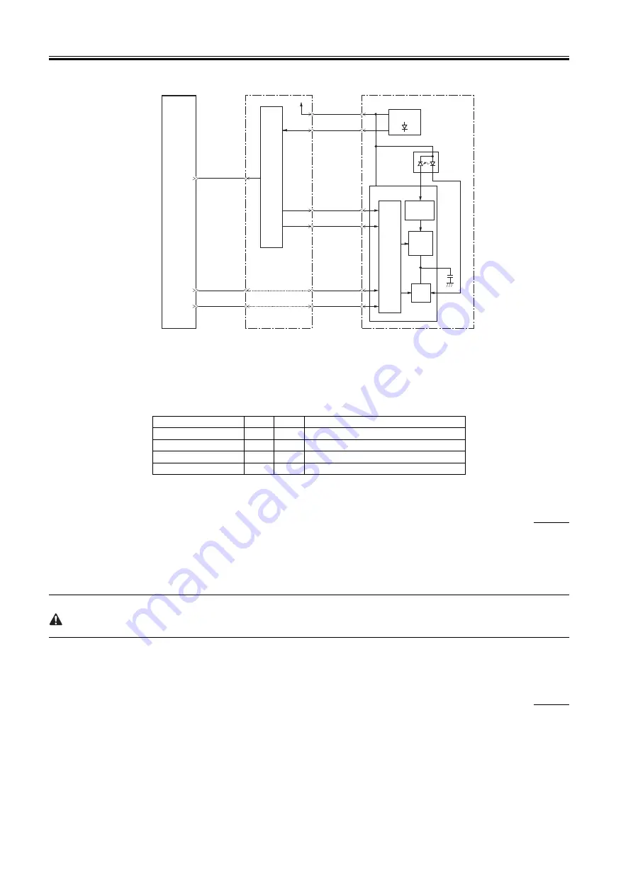
F-2-3
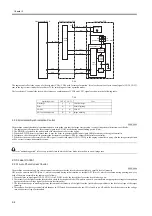
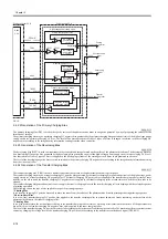
The engine controller is the source of video signals (VDO, /VDO) used for image formation. It is also the source of laser control signals (CNT0, CNT1)
sent to the logic circuit inside the laser driver IC for switching over laser operation modes.
The laser driver CI controls the laser with reference to combinations of CTN0 and CNT1 signals as shown in the following table:
T-2-2
2.3.2.2 Horizontal Synchronization Control
0008-0093
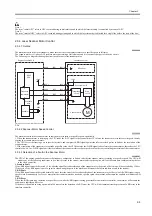
The machine controls horizontal synchronization so as to make sure that the image start position is correct in horizontal direction; specifically,
1. The engine controller turns the laser control signal into LD APC mode during an unblanking period (Note).
2. The BD PCB is located in the optical path of the laser beam to detect the beam.
3. When the BD PCB detects the laser beam, it uses the beam to generate the BD input signal (/BDI) for output to the engine controller.
4. In response, the video controller generates the horizontal sync signal (/BD) for output to the interface controller.
5. When the video controller receives the /BD signal, it sends video signals (VDO, /VDO) to the engine controller in a way that the image start position
will be correct in image horizontal direction.
The term "unblanking period" refers to a period of time in which the laser diode is turned on in a non-image area.
2.3.3 Laser Control
2.3.3.1 Auto Photo Current Control
0008-0094
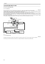
The machine executes auto photo current control to make sure that the laser diode emits light at a specific level of intensity.
APC may be either initial APC (Note 1), which is executed during initial rotation, or interval APC (Note 2), which is executed during printing; however,
both of them are executed in the same way as follows:
1. When the laser control signal (CNT0, CNT1) is in LD APC mode, the laser driver forces the laser diode to go on.
2. The intensify of the light from the laser diode is checked by the photodiode (PD), and its current is converted into an appropriate voltage for comparison
against a reference voltage (equal to the target laser intensity).
3. The laser driver keeps controlling the laser current until the intensity of the light from the laser diode is equivalent to the level of voltage of the target
intensity.
4. Thereafter, when the laser control signal changes to LD forced deactivation mode, the LD is forced to go off, and the laser driver converts the voltage
into a capacitor voltage for retention.
Operating mode
CNT0
CNT1
Uses
Discharge
L
L
C803 discharge
H
L
Normal printing
LD APC
L
H
LD APC
LD forced deactivation
H
H
Image masking
J801-8
-9
-5
-6
-3
-2
/BDI
CNT1
CNT0
VDO
/VDO
IC902
CPU
Laser driver PCB
+5V
Video controller PCB
J904-8
-9
-5
-6
-3
-2
/BD
VDO
/VDO
J910-10
-13
-12
PD
(photodiode)
LD
(laser diode)
Laser driver IC
C803
Engine controller PCB
BD sensor
Comparator
Sample
hold
circuit
Drive
circuit
Logic
circuit
Summary of Contents for LBP-3000
Page 1: ...H T T P W W W F I X C L U B C O M C N Mar 10 2005 Service Manual LBP3000 2900 Series LBP2900 ...
Page 2: ...H T T P W W W F I X C L U B C O M C N ...
Page 6: ...H T T P W W W F I X C L U B C O M C N ...
Page 12: ...H T T P W W W F I X C L U B C O M C N Contents ...
Page 13: ...H T T P W W W F I X C L U B C O M C N Chapter 1 PRODUCT DESCRIPTION ...
Page 14: ...H T T P W W W F I X C L U B C O M C N ...
Page 16: ...H T T P W W W F I X C L U B C O M C N ...
Page 23: ...H T T P W W W F I X C L U B C O M C N Chapter 2 TECHNICAL REFERENCE ...
Page 24: ...H T T P W W W F I X C L U B C O M C N ...
Page 44: ...H T T P W W W F I X C L U B C O M C N Chapter 2 2 18 ...
Page 51: ...H T T P W W W F I X C L U B C O M C N Chapter 3 DISASSEMBLY AND ASSEMBLY ...
Page 52: ...H T T P W W W F I X C L U B C O M C N ...
Page 87: ...H T T P W W W F I X C L U B C O M C N Chapter 3 3 33 F 3 161 ...
Page 88: ...H T T P W W W F I X C L U B C O M C N ...
Page 89: ...H T T P W W W F I X C L U B C O M C N Chapter 4 MAINTENANCE AND INSPECTION ...
Page 90: ...H T T P W W W F I X C L U B C O M C N ...
Page 92: ...H T T P W W W F I X C L U B C O M C N ...
Page 98: ...H T T P W W W F I X C L U B C O M C N ...
Page 99: ...H T T P W W W F I X C L U B C O M C N Chapter 5 TROUBLESHOOTING ...
Page 100: ...H T T P W W W F I X C L U B C O M C N ...
Page 102: ...H T T P W W W F I X C L U B C O M C N ...
Page 107: ...H T T P W W W F I X C L U B C O M C N Chapter 6 APPENDIX ...
Page 108: ...H T T P W W W F I X C L U B C O M C N ...
Page 110: ...H T T P W W W F I X C L U B C O M C N ...
Page 117: ...H T T P W W W F I X C L U B C O M C N Mar 10 2005 ...


