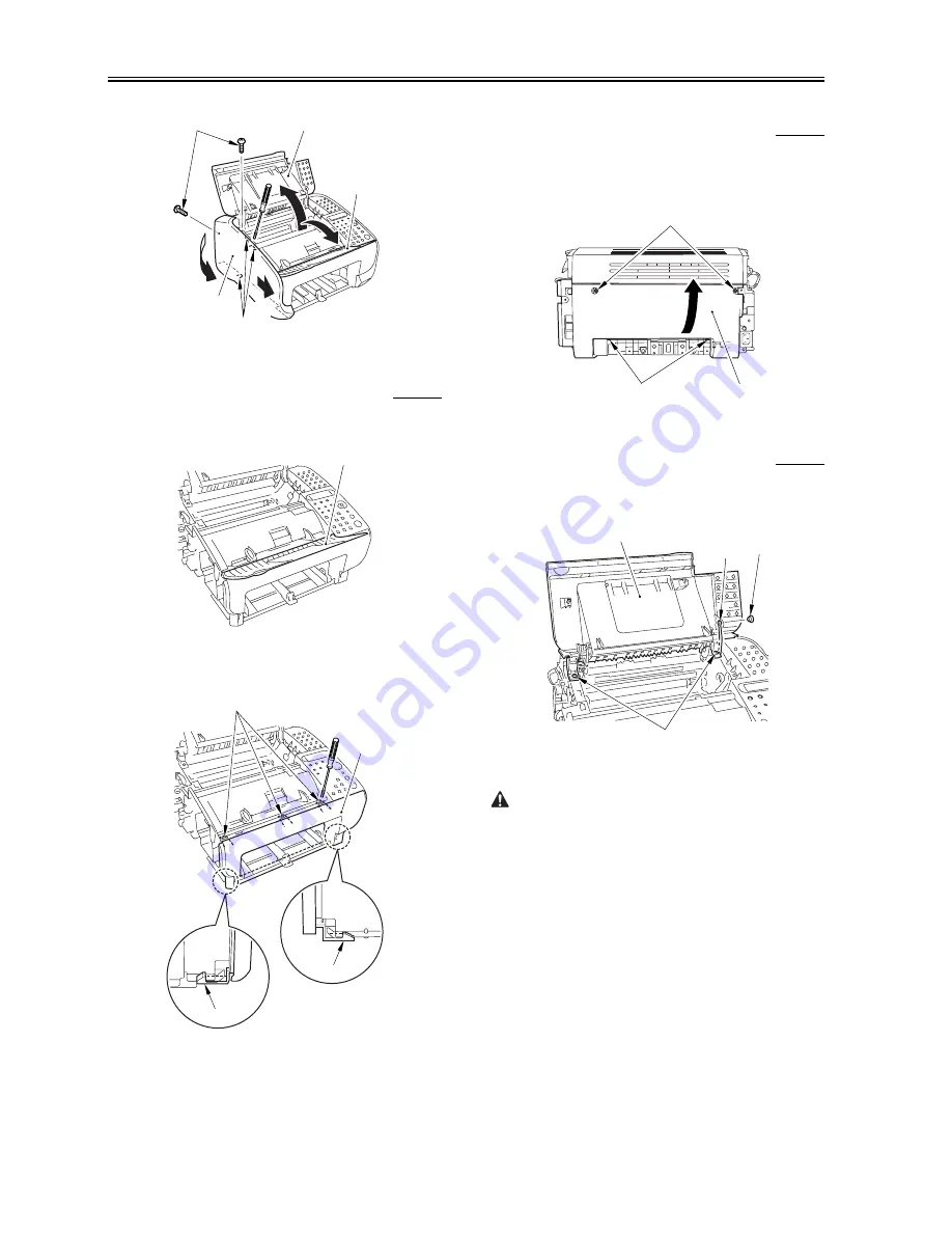
Canon L120 Series Service Manual Download Page 60

Chapter 3  

3-6

F-3-25

3.1.7.3 Removing the Front Cover

0010-3472

FAX-L100 / FAX-L120

1) Wrap the document feeder tray [1] slightly to detach.

F-3-26

2) Free the 3 claws [1], and detach the front cover [3] while freeing the

other 2 clows [2].

F-3-27

3.1.7.4 Removing the Rear Cover

0010-3473

FAX-L100 / FAX-L120

1) Remove the 2 screws [1].

2) Free the 2 claws [2], and detach the rear cover [3] while sliding it in

the direction of the arrow.

F-3-28

3.1.7.5 Removing the Cartridge Cover

0010-3474

FAX-L100 / FAX-L120

1) Free the link stop [2] from the door link [1].

2) Remove the 2 screws [3], and detach the cartridge cover [4].

F-3-29

When mounting the cartridge  cover, be sure to fit the 2 fixing assembly

release hooks [2] in the 2 hook holes [1] found in the cartridge cover.

[1]

[2]

[4]

[B]

[A]

[5]

[3]

[1]

[1]

[2]

[2]

[3]

[1]

[2]

[3]

[4]

[1]

[3]

[2]

Summary of Contents for L120 Series

Page 1: ...Jun 6 2005 Service Manual L100 L120 Series...

Page 2: ......

Page 3: ...need arises In the event of major changes in the contents of this manual over a long or short period Canon will issue a new edition of this manual The following paragraph does not apply to any countri...

Page 4: ...uiring care to avoid combustion fire Indicates an item prohibiting disassembly to avoid electric shocks or problems Indicates an item requiring disconnection of the power plug from the electric outlet...

Page 5: ...ed to indicate Low The voltage value how ever differs from circuit to circuit In addition the asterisk as in DRMD indicates that the DRMD signal goes on when 0 In practically all cases the internal me...

Page 6: ......

Page 7: ...ment Feed and Exposure System 2 1 2 1 1 Overview Configuration 2 1 2 1 1 1 Overview 2 1 2 2 Laser Exposure 2 2 2 2 1 Overview Configuration 2 2 2 2 1 1 Overview 2 2 2 3 Image Formation 2 4 2 3 1 Overv...

Page 8: ...t Cover 3 5 3 1 7 2 Removing the Left Cover 3 5 3 1 7 3 Removing the Front Cover 3 6 3 1 7 4 Removing the Rear Cover 3 6 3 1 7 5 Removing the Cartridge Cover 3 6 3 1 7 6 Removing the Operation Panel U...

Page 9: ...3 2 1 3 Removing the Front Cover 3 18 3 2 1 4 Removing the Rear Cover 3 18 3 2 1 5 Removing the Cartridge Cover 3 18 3 2 1 6 Removing the Operation Panel Unit 3 19 3 2 1 7 Removing the Upper Cover 3...

Page 10: ...moving the Right Cover 3 32 3 2 7 2 Removing the Left Cover 3 32 3 2 7 3 Removing the Front Cover 3 33 3 2 7 4 Removing the Rear Cover 3 33 3 2 7 5 Removing the Cartridge Cover 3 33 3 2 7 6 Removing t...

Page 11: ...the Left Cover 3 48 3 6 1 3 Removing the Front Cover 3 48 3 6 1 4 Removing the Rear Cover 3 48 3 6 1 5 Removing the Cartridge Cover 3 48 3 6 1 6 Removing the Operation Panel Unit 3 49 3 6 1 7 Removing...

Page 12: ...5 4 1 Outline 5 5 5 4 1 1 Error Code 5 5 5 5 Service Mode 5 9 5 5 1 Outline 5 9 5 5 1 1 Service Data Setting 5 9 5 5 1 2 Service Data Entry Method 5 9 5 5 1 3 Service Data Flowchart 5 9 5 5 2 Default...

Page 13: ...Chapter 1 PRODUCT DESCRIPTION...

Page 14: ......

Page 15: ...2 Printing Range Reception 1 7 1 2 3 Printing Range Printer 1 8 1 2 4 System Requirements for Printer Driver 1 9 1 3 Names of Parts 1 11 1 3 1 External View 1 11 1 3 2 Operation panel 1 12 1 4 Safety...

Page 16: ......

Page 17: ...7 7 line mm 195 58 dpi Super Fine 8 dots mm 203 2 dpi x 15 4 line mm 391 16 dpi Copying resolution Scanning 200 x 300 dpi Printing resolution 600 x 600 dpi Print speed A4 Approx 12 pages minute Warm u...

Page 18: ...2k 9 6k 7 2k 4 8k 2 4k bps With automatic fallback fuction Coding method MH MR MMR Error correction method ITU T ECM Minimum transmission time 10 msec MH MR 0 msec MMR Transmission output level 4 to...

Page 19: ...REPORT MEMORY DATA LIST MEMORY IMAGE PRINT MACHINE STATUS LIST Service report Service data list Others Directory function Yes Transmitting terminal identification None Completion stamp None Summer ti...

Page 20: ...reproduction 99 sheets Energy save mode None Operating environment Temperature range 15 to 30 deg C Operating environment Humidity range 10 to 80 RH Operating noise 30 dB or less Standby 50 dB or less...

Page 21: ...cast transmission None Polling transmission Direct transmission None Memory transmission Yse FAX TEL switching Method CNG detection Message None Pseudo CI None Pseudo ring Yse Pseudo ringback tone Yes...

Page 22: ...Chapter 1 1 6 Others Directory function Yes Transmitting terminal identification None Completion stamp None Summer time function Yes Residual Cartridge detecting Yes...

Page 23: ...margin 3 Effective scanning width 8 Scanning drop out range 4 Right margin 9 Scanning range 5 Top margin 10 Document trailing edge Item A4 Letter Legal Effective scanning width 208 1 0 1 0 mm 214 1 0...

Page 24: ...g range 5 Top margin 10 Paper trailing edge Item A4 Letter Legal Effective printing width 206 2 0 2 0 mm 212 2 0 2 0 mm 212 2 0 2 0 mm Effective printing length 290 3 0 3 0 mm 272 4 3 0 3 0 mm 348 6 3...

Page 25: ...m Right margin 4 0 2 0 2 0 mm 4 0 2 0 2 0 mm 4 0 2 0 2 0 mm Top margin 5 0 2 0 2 0 mm 5 0 2 0 2 0 mm 5 0 2 0 2 0 mm Bottom margin 6 0 5 0 5 0 mm 6 0 5 0 5 0 mm 6 0 5 0 5 0 mm OS CPU RAM Available Free...

Page 26: ...Chapter 1 1 10 Log on as a user with adoministrator privileges is recommended...

Page 27: ...livery tray H Automatic document feeder ADF B Paper delivery tray extension I Document feeder tray C Cartridge cover J Document feeder tray extention D Notch K Document delivery tray E Operation panel...

Page 28: ...9 1 3 2 Operation panel 0010 2185 FAX L100 FAX L120 N Handset Optional R External device jack O Handset cradle Optional S Line jack P USB port L120 only T Handset cable retainer Q Handset jack U Powe...

Page 29: ...nu button N Copy button E Status button O Left Right button F Image Quality button P Up Down button G Directory button Q OK button H Coded dial button R Clear button I Redial Pause button S Stop Reset...

Page 30: ...laser scanner unit are identified by the following label 1 F 1 7 1 4 3 Safety of Toner 0002 8619 FAX L100 FAX L120 The machine s toner is a non toxic material composed of plastic iron and small amoun...

Page 31: ...703 FAX L100 FAX L120 The batteries must be replaced correctly to avoid explosion Do not replace any battery with one not indicated for the machine i e use one of the same type or equivalent Be sure t...

Page 32: ......

Page 33: ...Chapter 2 TECHNICAL REFERENCE...

Page 34: ......

Page 35: ...elay Jam 2 6 2 4 2 3 Stationary Jams 2 6 2 4 2 3 1 Pickup Stationary Jam 2 6 2 4 2 3 2 Delivery Stationary Jam 2 6 2 4 2 4 Other Jams 2 6 2 4 2 4 1 Wrap Jam 2 6 2 4 2 4 2 Initial Jam 2 6 2 4 2 4 3 Cov...

Page 36: ......

Page 37: ...s are separated one sheet each using differences in the coefficient of friction among the separation roller documents and separation guide After that the feeder roller feeds the document onto the read...

Page 38: ...e photosensitive drum Memo BD Fault The machine identifies a BD fault if it does not detect the BDI signal within 0 1 sec after the scanner motor is forced to accelerate It also detects a BD fault if...

Page 39: ...Chapter 2 2 3 The laser scanner unit contains parts that cannot be adjusted in the field Do not attempt to disassemble the laser scanner unit...

Page 40: ...The resulting toner image is then transferred to paper by the work of the transfer charging roller and the paper is sent to the fixing assembly The surface of the photosensitive drum is cleaned by the...

Page 41: ...nsor PS801 detects the leading edge of print paper that has been picked up 5 The SCNT board sends video signals to the laser scanner assembly based on the BD signal so as to form an image on the surfa...

Page 42: ...ted the leading edge of print paper 2 4 2 3 Stationary Jams 2 4 2 3 1 Pickup Stationary Jam 0010 2315 FAX L100 FAX L120 The CPU will detect the presence of a pickup stationary jam if the trailing edge...

Page 43: ...s of the print paper before it moves out of the fixing assembly Once outside the fixing assembly the print paper is delivered to the delivery tray by the work of the face down delivery roller upon det...

Page 44: ...the temperature of the fixing heater is lower than the target temperature thus preventing overheating of the fixing film 4 down sequence during continuous printing so as to prevent overheating of the...

Page 45: ...alent of 265 deg C the output of the comparator IC501 goes Low to turn off the transistor Q103 The fact will cause the relay RL101 to go off to cut off the power to the fixing heater regardless of the...

Page 46: ...The power supply circuit is equipped with 2 fuses FU1 FU2 in the event an overcurrent flows into the AC line either of these fuses will melt to cut out the current 2 6 1 2 Backup Battery 2 6 1 2 1 Bat...

Page 47: ...Chapter 3 DISASSEMBLY AND ASSEMBLY...

Page 48: ......

Page 49: ...Removing the Cartridge Cover 3 5 3 1 7 Operation Panel Unit 3 5 3 1 7 1 Removing the Right Cover 3 5 3 1 7 2 Removing the Left Cover 3 5 3 1 7 3 Removing the Front Cover 3 6 3 1 7 4 Removing the Rear...

Page 50: ...Cover 3 17 3 1 17 2 Removing the Speaker 3 17 3 2 Document Feed Exposure System 3 18 3 2 1 Separation Guide Unit 3 18 3 2 1 1 Removing the Right Cover 3 18 3 2 1 2 Removing the Left Cover 3 18 3 2 1 3...

Page 51: ...he Operation Panel Unit 3 31 3 2 6 7 Removing the Upper Cover 3 32 3 2 6 8 Removing the Reader Unit 3 32 3 2 6 9 Removing the Document Feed Motor 3 32 3 2 7 DS DES Sensor 3 32 3 2 7 1 Removing the Rig...

Page 52: ...Scanner Unit 3 47 3 5 5 11 Removing the Main Motor 3 47 3 6 FIXING SYSTEM 3 48 3 6 1 Fixing Unit 3 48 3 6 1 1 Removing the Right Cover 3 48 3 6 1 2 Removing the Left Cover 3 48 3 6 1 3 Removing the F...

Page 53: ...Contents 3 6 3 10 Removing the Fixing Film Unit 3 55 3 6 3 11 Removing the Pressure Roller 3 56...

Page 54: ......

Page 55: ...ews 3 4 Free the 4 claws 4 and detach the Left cover 5 in the direction of the arrow A then slide it in the direction of the other arrow B F 3 2 3 1 1 3 Removing the Front Cover 0010 3372 FAX L100 FAX...

Page 56: ...e cover 2 3 Remove the screw 3 4 Free the 3 claws 4 and open the right cover 5 in the direction of the arrow A 5 Free the claws 6 and detach the right cover 5 F 3 8 3 1 4 Left Cover 3 1 4 1 Removing t...

Page 57: ...FAX L120 1 Wrap the document feeder tray 1 slightly to detach F 3 12 2 Free the 3 claws 1 and detach the front cover 3 while freeing the other 2 clows 2 F 3 13 3 1 5 4 Removing the Rear Cover 0010 34...

Page 58: ...irection of the arrow F 3 18 3 1 6 Cartridge Cover 3 1 6 1 Removing the Right Cover 0010 3461 FAX L100 FAX L120 1 Open the document feeder tray 1 2 Open the cartridge cover 2 3 Remove the screw 3 4 Fr...

Page 59: ...in the cartridge cover F 3 23 3 1 7 Operation Panel Unit 3 1 7 1 Removing the Right Cover 0010 3470 FAX L100 FAX L120 1 Open the document feeder tray 1 2 Open the cartridge cover 2 3 Remove the screw...

Page 60: ...FAX L120 1 Remove the 2 screws 1 2 Free the 2 claws 2 and detach the rear cover 3 while sliding it in the direction of the arrow F 3 28 3 1 7 5 Removing the Cartridge Cover 0010 3474 FAX L100 FAX L120...

Page 61: ...irection of the arrow A 5 Free the claws 6 and detach the right cover 5 F 3 32 3 1 8 2 Removing the SCNT Board 0010 3655 FAX L100 FAX L120 1 Remove the flat cable 1 and disconnect the 7 connectors 2 2...

Page 62: ...FAX L120 1 Wrap the document feeder tray 1 slightly to detach F 3 36 2 Free the 3 claws 1 and detach the front cover 3 while freeing the other 2 clows 2 F 3 37 3 1 9 4 Removing the Rear Cover 0010 35...

Page 63: ...3607 FAX L100 FAX L120 1 Disconnect the 3 connectors 1 2 Remove the screw 2 3 Free the harness 4 from the clamp 3 4 Remove the 3 screws 5 and detach the reader unit 5 F 3 42 3 1 9 8 Removing the DCNT...

Page 64: ...nectors 1 2 Remove the 5 screws 2 and detach the power supply board 3 F 3 48 3 1 11 High voitage Power Supply PCB 3 1 11 1 Removing the Right Cover 0010 3398 FAX L100 FAX L120 1 Open the document feed...

Page 65: ...cartridge cover be sure to fit the 2 fixing assembly release hooks 2 in the 2 hook holes 1 found in the cartridge cover F 3 53 3 1 11 5 Removing the Rear Plate 0010 3483 FAX L100 FAX L120 1 Remove the...

Page 66: ...om the clamp 3 3 Disconnect the connector 5 4 Remove the screw 6 and detach the DC DC converter board 7 F 3 58 3 1 13 Top Sensor 3 1 13 1 Removing the Right Cover 0010 3634 FAX L100 FAX L120 1 Open th...

Page 67: ...ge cover be sure to fit the 2 fixing assembly release hooks 2 in the 2 hook holes 1 found in the cartridge cover F 3 63 3 1 13 5 Removing the Rear Plate 0010 3638 FAX L100 FAX L120 1 Remove the screw...

Page 68: ...etach the Left cover 5 in the direction of the arrow A then slide it in the direction of the other arrow B F 3 67 3 1 14 3 Removing the Rear Cover 0010 3648 FAX L100 FAX L120 1 Remove the 2 screws 1 2...

Page 69: ...1 Removing the Right Cover 0010 3756 FAX L100 FAX L120 1 Open the document feeder tray 1 2 Open the cartridge cover 2 3 Remove the screw 3 4 Free the 3 claws 4 and open the right cover 5 in the direct...

Page 70: ...ach the Left cover 5 in the direction of the arrow A then slide it in the direction of the other arrow B F 3 78 3 1 16 3 Removing the Rear Cover 0010 3642 FAX L100 FAX L120 1 Remove the 2 screws 1 2 F...

Page 71: ...0 3401 FAX L100 FAX L120 1 Open the document feeder tray 1 2 Open the cartridge cover 2 3 Remove the screw 3 4 Free the 3 claws 4 and open the right cover 5 in the direction of the arrow A 5 Free the...

Page 72: ...2 3 Remove the 2 screws 3 4 Free the 4 claws 4 and detach the Left cover 5 in the direction of the arrow A then slide it in the direction of the other arrow B F 3 86 3 2 1 3 Removing the Front Cover...

Page 73: ...moving the Upper Cover 0010 3686 FAX L100 FAX L120 1 Remove the screw 1 2 Free the claw 2 and detach the upper cover 3 in the direction of the arrow F 3 93 3 2 1 8 Removing the Reader Unit 0010 3687 F...

Page 74: ...of the arrow A 5 Free the claws 6 and detach the right cover 5 F 3 98 3 2 2 2 Removing the Left Cover 0010 3748 FAX L100 FAX L120 1 Open the document feeder tray 1 2 Open the cartridge cover 2 3 Remo...

Page 75: ...ink stop 2 from the door link 1 2 Remove the 2 screws 3 and detach the cartridge cover 4 F 3 103 When mounting the cartridge cover be sure to fit the 2 fixing assembly release hooks 2 in the 2 hook ho...

Page 76: ...ach the reader unit 5 F 3 107 3 2 2 9 Removing the Contact Sensor 0010 3755 FAX L100 FAX L120 1 Free the harness 1 from the cable guide 2 2 Open the lower reader unit frame 3 and free the claw 4 F 3 1...

Page 77: ...Left cover 5 in the direction of the arrow A then slide it in the direction of the other arrow B F 3 113 3 2 3 3 Removing the Front Cover 0010 3781 FAX L100 FAX L120 1 Wrap the document feeder tray 1...

Page 78: ...Removing the Upper Cover 0010 3785 FAX L100 FAX L120 1 Remove the screw 1 2 Free the claw 2 and detach the upper cover 3 in the direction of the arrow F 3 120 3 2 3 8 Removing the Reader Unit 0010 378...

Page 79: ...pen the right cover 5 in the direction of the arrow A 5 Free the claws 6 and detach the right cover 5 F 3 125 3 2 4 2 Removing the Left Cover 0010 3699 FAX L100 FAX L120 1 Open the document feeder tra...

Page 80: ...cover 4 F 3 130 When mounting the cartridge cover be sure to fit the 2 fixing assembly release hooks 2 in the 2 hook holes 1 found in the cartridge cover F 3 131 3 2 4 6 Removing the Operation Panel...

Page 81: ...1 Free the claw 1 and detach the upper reader unit frame 2 F 3 135 3 2 4 10 Removing the Document Feed Roller 0010 3707 FAX L100 FAX L120 1 Free the harness 1 from the cable guide 2 2 Remove the 2 scr...

Page 82: ...cover 5 F 3 141 3 2 5 2 Removing the Left Cover 0010 3600 FAX L100 FAX L120 1 Open the document feeder tray 1 2 Open the cartridge cover 2 3 Remove the 2 screws 3 4 Free the 4 claws 4 and detach the...

Page 83: ...cover 4 F 3 146 When mounting the cartridge cover be sure to fit the 2 fixing assembly release hooks 2 in the 2 hook holes 1 found in the cartridge cover F 3 147 3 2 5 6 Removing the Operation Panel...

Page 84: ...cover 5 in the direction of the arrow A 5 Free the claws 6 and detach the right cover 5 F 3 151 3 2 6 2 Removing the Left Cover 0010 3658 FAX L100 FAX L120 1 Open the document feeder tray 1 2 Open th...

Page 85: ...ink stop 2 from the door link 1 2 Remove the 2 screws 3 and detach the cartridge cover 4 F 3 156 When mounting the cartridge cover be sure to fit the 2 fixing assembly release hooks 2 in the 2 hook ho...

Page 86: ...e 2 2 Remove the 2 screws 3 and detach the Document feed motor 4 F 3 161 3 2 7 DS DES Sensor 3 2 7 1 Removing the Right Cover 0010 3735 FAX L100 FAX L120 1 Open the document feeder tray 1 2 Open the c...

Page 87: ...FAX L120 1 Remove the 2 screws 1 2 Free the 2 claws 2 and detach the rear cover 3 while sliding it in the direction of the arrow F 3 166 3 2 7 5 Removing the Cartridge Cover 0010 3740 FAX L100 FAX L1...

Page 88: ...8 Removing the Reader Unit 0010 3743 FAX L100 FAX L120 1 Disconnect the 3 connectors 1 2 Remove the screw 2 3 Free the harness 4 from the clamp 3 4 Remove the 3 screws 5 and detach the reader unit 5 F...

Page 89: ...Chapter 3 3 35 F 3 173 3 Remove the 6 gears 1 F 3 174 4 Remove the 7 screws 1 and detach the cover 2 F 3 175 5 Free the 4 claws 1 and detach the DS DES sensor 2 F 3 176 4 3 2 1 1 1 1 1 2 1 2 1 2...

Page 90: ...move the 2 screws 3 4 Free the 4 claws 4 and detach the Left cover 5 in the direction of the arrow A then slide it in the direction of the other arrow B F 3 178 3 3 1 3 Removing the Front Cover 0010 3...

Page 91: ...nit 4 F 3 184 3 3 1 7 Removing the Upper Cover 0010 3618 FAX L100 FAX L120 1 Remove the screw 1 2 Free the claw 2 and detach the upper cover 3 in the direction of the arrow F 3 185 3 3 1 8 Removing th...

Page 92: ...he screw 4 and turn over the DCNT board 5 F 3 189 7 Disconnect the 2 connectors 1 8 Remove the 2 screws 2 and detach the DCNT board 4 from the plate 3 F 3 190 3 3 1 10 Removing the Laser Scanner Unit...

Page 93: ...artridge cover 3 Free the 2 claws 1 of the Transfer charging roller 4 Free the 2 claws 2 of the Transfer guide 5 Detach the Transfer charging roller 4 together with the transfer guide 3 6 Detach the T...

Page 94: ...ver 0010 3537 FAX L100 FAX L120 1 Open the document feeder tray 1 2 Open the cartridge cover 2 3 Remove the screw 3 4 Free the 3 claws 4 and open the right cover 5 in the direction of the arrow A 5 Fr...

Page 95: ...ink stop 2 from the door link 1 2 Remove the 2 screws 3 and detach the cartridge cover 4 F 3 199 When mounting the cartridge cover be sure to fit the 2 fixing assembly release hooks 2 in the 2 hook ho...

Page 96: ...late 2 in the direction of the arrow F 3 203 3 5 1 10 Removing the Fixing Assembly 0010 3553 FAX L100 FAX L120 1 Disconnect the 5 connectors 1 2 Free the harness 3 from the cable guide 2 F 3 204 3 Dis...

Page 97: ...laws 4 and open the right cover 5 in the direction of the arrow A 5 Free the claws 6 and detach the right cover 5 F 3 210 3 5 3 2 Removing the Pickup Solenoid 0010 3391 FAX L100 FAX L120 1 Remove the...

Page 98: ...of the arrow A 5 Free the claws 6 and detach the right cover 5 F 3 216 3 5 5 2 Removing the Left Cover 0010 3624 FAX L100 FAX L120 1 Open the document feeder tray 1 2 Open the cartridge cover 2 3 Rem...

Page 99: ...ink stop 2 from the door link 1 2 Remove the 2 screws 3 and detach the cartridge cover 4 F 3 221 When mounting the cartridge cover be sure to fit the 2 fixing assembly release hooks 2 in the 2 hook ho...

Page 100: ...ve the 3 screws 5 and detach the reader unit 5 F 3 225 3 5 5 9 Removing the DCNT board 0010 3631 FAX L100 FAX L120 1 Remove the 2 screws 1 and detach the DCNT cover 1 2 2 Remove the 2 screws 3 and det...

Page 101: ...r Scanner Unit 0010 3632 FAX L100 FAX L120 1 Remove the 4 screws 1 and detach the Laser Scanner unit 2 F 3 230 3 5 5 11 Removing the Main Motor 0010 3633 FAX L100 FAX L120 1 Remove the 2 screws 1 and...

Page 102: ...e 2 screws 3 4 Free the 4 claws 4 and detach the Left cover 5 in the direction of the arrow A then slide it in the direction of the other arrow B F 3 233 3 6 1 3 Removing the Front Cover 0010 3488 FAX...

Page 103: ...ee the claw 3 and detach the operation panel unit 4 F 3 239 3 6 1 7 Removing the Upper Cover 0010 3492 FAX L100 FAX L120 1 Remove the screw 1 2 Free the claw 2 and detach the upper cover 3 in the dire...

Page 104: ...laws 6 and detach the right cover 5 F 3 245 3 6 2 2 Removing the Left Cover 0010 3571 FAX L100 FAX L120 1 Open the document feeder tray 1 2 Open the cartridge cover 2 3 Remove the 2 screws 3 4 Free th...

Page 105: ...ink stop 2 from the door link 1 2 Remove the 2 screws 3 and detach the cartridge cover 4 F 3 250 When mounting the cartridge cover be sure to fit the 2 fixing assembly release hooks 2 in the 2 hook ho...

Page 106: ...n the direction of the arrow F 3 254 3 6 2 9 Removing the Fixing Assembly 0010 3578 FAX L100 FAX L120 1 Disconnect the 5 connectors 1 2 Free the harness 3 from the cable guide 2 F 3 255 3 Disconnect t...

Page 107: ...row A 5 Free the claws 6 and detach the right cover 5 F 3 261 3 6 3 2 Removing the Left Cover 0010 3581 FAX L100 FAX L120 1 Open the document feeder tray 1 2 Open the cartridge cover 2 3 Remove the 2...

Page 108: ...ink stop 2 from the door link 1 2 Remove the 2 screws 3 and detach the cartridge cover 4 F 3 266 When mounting the cartridge cover be sure to fit the 2 fixing assembly release hooks 2 in the 2 hook ho...

Page 109: ...n the direction of the arrow F 3 270 3 6 3 9 Removing the Fixing Assembly 0010 3589 FAX L100 FAX L120 1 Disconnect the 5 connectors 1 2 Free the harness 3 from the cable guide 2 F 3 271 3 Disconnect t...

Page 110: ...releasing levers 2 4 Remove the 2 locking plate 3 and detach the fixing film unit 4 F 3 276 3 6 3 11 Removing the Pressure Roller 0010 3591 FAX L100 FAX L120 1 Free the claw 1 and remove the gear 2 t...

Page 111: ...Chapter 4 MAINTENANCE AND INSPECTION...

Page 112: ......

Page 113: ...4 1 4 1 1 Periodic Replacement Parts 4 1 4 2 Consumables 4 2 4 2 1 Consumable 4 2 4 3 Cleaning 4 3 4 3 1 Items Requiring Cleaning 4 3 4 3 2 Cleaning Method external covers 4 3 4 3 3 Cleaning Method s...

Page 114: ......

Page 115: ...Chapter 4 4 1 4 1 Periodically Replaced Parts 4 1 1 Periodic Replacement Parts 0003 0867 FAX L100 FAX L120 No parts require periodic replacement in this printer...

Page 116: ...er 4 4 2 4 2 Consumables 4 2 1 Consumable 0010 2420 FAX L100 FAX L120 T 4 1 Work by Item Interval guide User Cartridge FX 10 When toner in the toner cartridge being used has run out Service Techician...

Page 117: ...copied or transmitted images White sheet When image scanned from the ADF becomes lighter Service technician Document pickup roller When document pickup performance has lowered Document separation roll...

Page 118: ...hite sheet Open the Lower reader unit frame and wipe off the dirt with a soft dry cloth 5 Document delivery roller Open the Lower reader unit frame and wipe off the dirt with a soft dry cloth 6 Scanni...

Page 119: ...Dry wipe with lint free paper 3 Static Eliminator Clean with a brush 4 Pickup Roller Dry wipe with lint free paper 5 Separation Pad Dry wipe the rubber portion with lint free paper 6 Feed Roller Dry w...

Page 120: ......

Page 121: ...Chapter 5 TROUBLESHOOTING...

Page 122: ......

Page 123: ...it 2 and Bit 3 5 19 5 5 3 3 SSSW SW10 5 20 5 5 3 3 1 List of Functions 5 20 5 5 3 3 2 Details of Bit 1 5 20 5 5 3 3 3 Details of Bit 2 5 20 5 5 3 4 SSSW SW16 5 20 5 5 3 4 1 List of Functions 5 20 5 5...

Page 124: ...Contents 5 5 5 2 3 Sensor Tests 5 24 5 5 5 2 4 Operation Panel Tests 5 24...

Page 125: ...c Intervals Initial Offset in a Low Temperature Humidity Environment Black Lines Caused by Drum Memory Malfunction The Session No of Activiry report is reset each time the power is turned off and then...

Page 126: ...3 ADF SUB REGIST Use it to adjust the read start position when the ADF is used T 5 4 5 2 1 3 Print Adjustment 0010 3254 FAX L100 FAX L120 Press the Menu button and then the button to select ADJUST th...

Page 127: ...mm 99 1 0 5 mm 100 0 101 1 0 5 mm 102 2 1 0 mm 103 3 1 5 mm 104 4 2 0 mm 105 5 2 5 mm 106 6 3 0 mm 107 7 3 5 mm 108 8 4 0 mm 109 9 4 5 mm 110 10 5 0 mm Setting value Contents 90 10 5 0 mm 91 9 4 5 mm...

Page 128: ...ol Cleaning plastic note rubber metal oil and toner stains Alcohol Flammable keep away from flame Purchase locally 2 Lubricant Apply to gears between shaft and bushing Special oil Special solid lubric...

Page 129: ...not be using a G3 fax machine 0010 Received DCN signal after sending DTC signal in Polling Rx 0011 The number of re transmissions of the procedure signal has been exceeded 0012 Remote side Password no...

Page 130: ...6 sec 005F Can t detect silence after sending JM signal for polling Tx function 0060 There are no any bullietin files to be polled in V34 0061 Machine cannot detect V 21 or V 8 signal with 35 seconds...

Page 131: ...D sending MPS 3 times consecutively but no answer from receiveing unit 00CA After sending EOP signal the received is not one of MCF RTN PIP PIN PRI EOP DCN 00CB After sending EOP signal the received...

Page 132: ...hase D transmitting units out EOR_EOP 3 times consecutivery but not answer 00F6 Received incorrect response after sending EOR_EOP signal 00F7 After received ERR our side can t received response after...

Page 133: ...to indicate version information on the display SOFT SWITCH Use it to make settings that relate to basic fax service functions as for correcting communication problems REPORT Use it to output reports...

Page 134: ...MF LOW FREQ LEVEL CNG LEVEL CED LEVEL ECM MODE CODING SCHEME 2mm 0 to 5 2mm 0 to 5 2mm 0 to 5 33600 bps 33600 to 2400 33600 bps 33600 to 2400 10dBm 4 to 15 5dBm 8dBm 10dBm 10dBm ON OFF MMR MR MH Not u...

Page 135: ...d Not used Not used Not used 1 2 3 4 5 6 7 8 SW01 SW02 SW07 SW08 SW09 SW10 SW16 SW17 SW18 SW19 SW20 SW21 SW22 SW23 SW24 SW30 SW37 SW51 SW52 SW53 SW54 0 0 1 0 0 1 0 0 0 0 0 0 0 1 1 SW55 SW64 SW03 SW06...

Page 136: ...0000 00000000 00000000 SW28 11100101 11100101 11100101 11100101 11100001 11100101 SW29 11110000 11110000 11110000 11110000 11110000 11110000 SW30 00010110 10011010 00010110 00010110 00010110 00010110...

Page 137: ...10 00000110 00000111 00000110 SW21 00000100 00000100 00000100 00000100 00000100 00000100 SW22 10101000 10101000 10101000 10101000 10101000 10101000 SW23 00010010 00010010 00010010 00010010 00010010 00...

Page 138: ...SW12 00110001 01110001 01110001 01110001 00110001 00110001 SW13 01001000 01001000 01001000 01001000 01001000 01001000 SW14 01000000 01000000 01000000 01000000 01000000 01000000 SW15 10110101 10110101...

Page 139: ...00000000 00000000 00000000 00000000 00000000 00000000 SW05 00000011 00000000 00000000 00000011 10000011 00000011 SW06 00000000 00000000 00000000 00000000 00000000 00000000 SW07 10100000 10100000 10100...

Page 140: ...SW61 11110000 11110000 11110000 11110000 11110000 11110000 SW62 00000000 00000000 00000000 00000000 00000000 00000000 SW63 00000000 00000000 00000000 00000000 00000000 00000000 SW64 00000000 00000000...

Page 141: ...0000 00000000 00000000 00000000 00000000 SW52 10000011 10000011 10000011 10000011 10000011 10000011 SW53 10000011 10000011 10000011 10000011 10000011 10000011 SW54 00000011 00000011 00000001 00000011...

Page 142: ...01010001 01010001 01010001 01010001 SW37 00000000 00000000 00000000 00000000 00000000 SW38 10000000 10000000 10000000 10000000 10000000 SW39 10000000 10000000 10000000 10000000 10000000 SW40 00000000...

Page 143: ...r lines to the total number of lines per page of the received image The combination of bit 2 and bit 3 will bring about the following T 5 18 Bit Function 1 0 1 Not used 2 RTN signal transmission condi...

Page 144: ...00 FAX L120 T 5 20 5 5 3 4 2 Details of Bit 3 0010 4079 FAX L100 FAX L120 The document reading width can be selected When selecting the LTR size a LTR size document can be read in the LTR width 214 mm...

Page 145: ...800 and 2400 The following will be ture depending on the combination of bit 1 through bit 6 at time of transmission T 5 24 at time of reception T 5 25 2 Not used 3 Not used 4 Not used 5 Not used 6 Not...

Page 146: ...010 4192 FAX L100 FAX L120 Use it to select the date time notation for reports the following will be true depending on the combination of bit 6 and bit 7 T 5 29 1 1 0 2800 0 0 1 2400 Bit Function 1 0...

Page 147: ...art 0010 2876 FAX L100 FAX L120 To operate the test mode after pressing the Menu key press the key and select SERVICE MODE After this select TEST MODE with the cursor keys and press the OK key To come...

Page 148: ...From the FUNCTION menu select ADF FEED TEST Use the test to make sure that the ADF function of the sheet reader unit operates normally 5 5 5 2 3 Sensor Tests 0010 3273 FAX L100 FAX L120 From the H W T...

Page 149: ...s time that all characters properly disappear when their one touch keys are pressed F 5 13 Character Operation key Character Operation key 0 9 Numeric key I R button A Copy button J Hook button B Add...

Page 150: ......

Page 151: ...Chapter 6 APPENDIX...

Page 152: ......

Page 153: ...Contents Contents 6 1 Outline of Electrical Components 6 1 6 1 1 Sensor 6 1 6 1 1 1 Arrangement of Sensors and Switches 6 1 6 1 2 PCBs 6 1 6 1 2 1 Arrangement of PCBs 6 1...

Page 154: ......

Page 155: ...sors and Switches 0010 4694 FAX L100 FAX L120 F 6 1 1 Document Sensor 2 Document Edge Sensor PS801 Top of page sensor PS802 Paper width sensor PS803 Paper delivery sensor PS804 Paper width sensor 6 1...

Page 156: ...Chapter 6 6 2 F 6 2 1 High Voltage Power Supply Board 2 Power Supply Board 3 DCNT Board 4 SCNT Board 2 1 3 4...

Page 157: ...Jun 6 2005...

Page 158: ......

Reviews: