


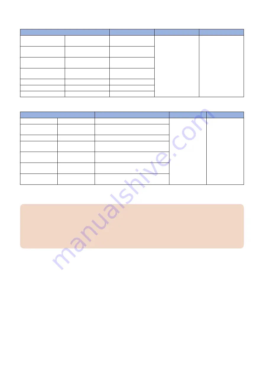
< When the Scanner is used (Semi-automatic Adjustment) >
Adjustment Items
Standard Values
Paper Source
Paper Size
Leading Edge Margin (1st
side)
REGIST1M
+/- 8 or less
3
A3 or 11x17
Left Edge Margin (2nd
side)
DIF-REFE
+/- 6 or less
Horizontal Scanning Mag-
nification Ratio
MAG-H-1M
+/- 20 or less
Vertical Scanning Magni-
fication Ratio
MAG-V-1M
+/- 20 or less
Lading Edge Skew
SLP-1M
+/- 6 or less
Leading Edge Right Angle
ANGLE-1M
+/- 6 or less
Trapezoid
TRPZ-1M
+/- 6 or less
< When the Scanner is not used (Manual Adjustment) >
Adjustment Items
Standard Values
Paper Source
Paper Size
Lading Edge Skew
SLP-1
L1 - L2 = +/- 0.6 mm
3
A3 or 11x17
Leading Edge Right
Angle
ANGLE-1
(L4 - L5) x 280/400 = +/- 0.6 mm
Trapezoid
TRPZ-1
Lx1 - Lx2 = +/- 0.6 mm
Horizontal Scanning
Magnification Ratio
MAG-H
A3: Ly = 292 +/- 0.6mm
11x17: Ly = 274.4 +/- 0.5 mm
Vertical Scanning
Magnification Ratio
MAG-V
A3: Lx = 412 +/- 0.8mm
11x17: Lx = 423.8 +/- 0.8 mm
Leading Edge Margin
(1st side)
REGIST
L3 = 4.0 +/- 0.8 mm
Left Edge Margin
(2nd side)
ADJ-REFE
L4 (2nd side) - L4 (1st side) = +/- 0.6 mm
■ Adjustment Procedure
CAUTION:
• The test print used for adjustment must be magenta halftone image.
• In the case of 2-sided output, the first side is printed on the lower side and the second side is printed on the
upper side.
• In the case of halftone images delivered face-down, the leading edge of the formed image comes to the trailing
edge side with respect to the feed direction at the time of output. Be sure to pay attention to the leading edge
and the trailing edge during measurement.
1. Set the service mode as follows and output the test print.
<1st side> Each paper source
COPIER > TEST > PG > TYPE = 5
COPIER > TEST > PG > COLOR-M = 1
COPIER > TEST > PG > COLOR-Y = 0
COPIER > TEST > PG > COLOR-C = 0
COPIER > TEST > PG > COLOR-Bk = 0
COPIER > TEST > PG > PG-PICK = 1/2/3/4/5
COPIER > TEST > PG > 2-SIDE = 0
<2nd side> Cassette 3
COPIER > TEST > PG > TYPE = 5
COPIER > TEST > PG > COLOR-M = 1
COPIER > TEST > PG > COLOR-Y = 0
COPIER > TEST > PG > COLOR-C = 0
COPIER > TEST > PG > COLOR-Bk = 0
COPIER > TEST > PG > PG-PICK = 3
COPIER > TEST > PG > 2-SIDE = 1
2. Host Machine
89
Summary of Contents for imagePRESS Lite C270
Page 10: ...Safety Precautions Toner Safety 2 Points to Note at Installation 2 ...
Page 34: ...1 Open the ADF 2 2 Host Machine 25 ...
Page 38: ...9 Store the Scanner Fixation Member 10 Store the Scanner Fixation Member 2 Host Machine 29 ...
Page 39: ...11 Install the Maintenance Cover Upper 12 2 Host Machine 30 ...
Page 141: ... Adjustment of the White Plate 1 2 Host Machine 132 ...
Page 152: ...2 3 2 Host Machine 143 ...
Page 156: ...9 10 11 2 Host Machine 147 ...
Page 157: ...12 Connect the power plug to the outlet 13 Turn ON the main power switch 2 Host Machine 148 ...
Page 158: ...Image Reading System Options 3 Printer Cover H2 150 Reader Heater P1 169 ...
Page 161: ...2 2x 3 4 1x 3 Image Reading System Options 152 ...
Page 162: ...5 3x 3 Image Reading System Options 153 ...
Page 163: ... Removing the ADF 1 1x 2x 3 Image Reading System Options 154 ...
Page 166: ...5 3x 6 3 Image Reading System Options 157 ...
Page 167: ...7 CAUTION Be careful not to drop the ADF 4x 3 Image Reading System Options 158 ...
Page 168: ... Removing the Reader Unit 1 3x 2 2x 2x 3 Image Reading System Options 159 ...
Page 169: ...3 3x 4 4x 3 Image Reading System Options 160 ...
Page 176: ... Installing the Covers 1 3x 2 1x 3 2x 3 Image Reading System Options 167 ...
Page 182: ...5 6 3x 1x 3 Image Reading System Options 173 ...
Page 183: ...7 1x 8 3x 3 Image Reading System Options 174 ...
Page 184: ...9 10 11 2x 3 Image Reading System Options 175 ...
Page 185: ...12 13 Middle 3 Image Reading System Options 176 ...
Page 186: ...14 15 2x Binding M4x4 3 Image Reading System Options 177 ...
Page 187: ...16 Small 17 1x 3 Image Reading System Options 178 ...
Page 188: ...18 7x 19 2x 3 Image Reading System Options 179 ...
Page 189: ...20 21 3x 1x 3 Image Reading System Options 180 ...
Page 193: ...25 26 3x 3 Image Reading System Options 184 ...
Page 194: ...27 1x 1x 28 29 1x 3 Image Reading System Options 185 ...
Page 199: ...Installation Procedure 1 2 4 Host Machine Options 190 ...
Page 200: ...3 4 5x 4 Host Machine Options 191 ...
Page 202: ...7 3x 8 2x 9 4 Host Machine Options 193 ...
Page 208: ...17 1x 1x 12x 18 3x 4 Host Machine Options 199 ...
Page 209: ...19 1x 20 2x 21 4 Host Machine Options 200 ...
Page 210: ...22 6x 23 5x 24 4 Host Machine Options 201 ...
Page 211: ...25 26 4 Host Machine Options 202 ...
Page 212: ...27 4 Host Machine Options 203 ...
Page 215: ...Installation Procedure 1 2 4 Host Machine Options 206 ...
Page 216: ...3 4 5 4 Host Machine Options 207 ...
Page 219: ...10 3x 1x 11 Large 4 Host Machine Options 210 ...
Page 220: ...12 1x 1x 4 Host Machine Options 211 ...
Page 225: ...2 2x 4 Host Machine Options 216 ...
Page 226: ...3 CAUTION To avoid damage do not pull the Utility Tray too much 4 Host Machine Options 217 ...
Page 229: ...8 2x 2x TP M4x10 9 4 Host Machine Options 220 ...
Page 230: ... When Installing the USB Keyboard 4 Host Machine Options 221 ...
Page 233: ...Installation Procedure 1 16x 4 Host Machine Options 224 ...
Page 234: ...2 NOTE 2x NOTE Removed Screw will be used in step 6 3 1x 4 Host Machine Options 225 ...
Page 235: ...4 4 Host Machine Options 226 ...
Page 237: ...7 16x 4 Host Machine Options 228 ...
Page 238: ...8 4 Host Machine Options 229 ...
Page 239: ...9 10 1x Binding M4x20 4 Host Machine Options 230 ...
Page 245: ...Installation Outline Drawing 4 Host Machine Options 236 ...
Page 246: ...Installation Procedure 1 16x 4 Host Machine Options 237 ...
Page 247: ...2 2x NOTE NOTE Removed Screw will be used in step 3 4 Host Machine Options 238 ...
Page 248: ...3 NOTE Use the screws removed in step 2 TP M3x6 NOTE 1x 2x 2x 1x 4 Host Machine Options 239 ...
Page 249: ...4 CAUTION When cutting off the part be sure not to make burrs 4 Host Machine Options 240 ...
Page 250: ...5 16x 6 4 Host Machine Options 241 ...
Page 251: ...7 2x Binding M4x20 8 1x Binding M4x6 4 Host Machine Options 242 ...
Page 253: ...10 11 1x 1x 4 Host Machine Options 244 ...
Page 256: ...Installation Outline Drawing 4 Host Machine Options 247 ...
Page 257: ...Installation Procedure 1 16x 4 Host Machine Options 248 ...
Page 258: ...2 2x NOTE NOTE Removed Screw will be used in step 3 4 Host Machine Options 249 ...
Page 259: ...3 NOTE Use the screws removed in step 2 TP M3x6 NOTE 1x 3x 1x 1x 4 Host Machine Options 250 ...
Page 260: ...4 CAUTION When cutting off the part be sure not to make burrs 4 Host Machine Options 251 ...
Page 261: ...5 16x 4 Host Machine Options 252 ...
Page 262: ...6 7 2x Binding M4x20 4 Host Machine Options 253 ...
Page 263: ...8 4 Host Machine Options 254 ...
Page 268: ...Copy Control Interface Kit A1 Installation Procedure 1 16x 4 Host Machine Options 259 ...
Page 269: ...2 2x 4 Host Machine Options 260 ...
Page 270: ...3 Serial Interface Kit K3 1x 4 Host Machine Options 261 ...
Page 271: ...Copy Control Interface Kit A1 1x 4 Host Machine Options 262 ...
Page 276: ...2 1x 1x 1x 1x 1x TP M3x6 3 Install the removed cover 4 Host Machine Options 267 ...
Page 282: ...Installation Outline Drawing 4 Host Machine Options 273 ...
Page 286: ...3 4x W Sems M3x8 4 Host Machine Options 277 ...
Page 287: ...4 9 7 mm 22 mm 6x 4x 4 Host Machine Options 278 ...
Page 288: ...5 5x 2x 6 3x 2x 7 Install the removed cover and telephone cord 4 Host Machine Options 279 ...
Page 293: ...1 16x 4 Host Machine Options 284 ...
Page 294: ...2 4 Host Machine Options 285 ...
Page 297: ...6 4 Host Machine Options 288 ...
Page 302: ...1 16x 4 Host Machine Options 293 ...
Page 303: ...2 1x 4 Host Machine Options 294 ...
Page 305: ...5 4 Host Machine Options 296 ...
Page 306: ...6 1x 4 Host Machine Options 297 ...
Page 307: ...7 1x 2x 4x 4 Host Machine Options 298 ...
Page 312: ...2 NOTE If screws and a face cover are attached remove them 4 Host Machine Options 303 ...
Page 314: ...5 8x 4 Host Machine Options 305 ...
Page 316: ...7 4x 8x 4 Host Machine Options 307 ...
Page 317: ...8 Toothed Washer Screw Binding M4x8 4x 4 Host Machine Options 308 ...
Page 318: ...9 4x 4 Host Machine Options 309 ...
Page 327: ...Installation Procedure 1 6x 2 3x 4 Host Machine Options 318 ...
Page 328: ...3 1x 4 4x 4x 4 Host Machine Options 319 ...
Page 329: ...5 2x M3x6 6 4 Host Machine Options 320 ...
Page 331: ...9 3x 10 4x 4 Host Machine Options 322 ...
Page 333: ...13 2x 4 Host Machine Options 324 ...
Page 341: ...14 Install the Connector 1x 15 Install the Connector Cover 5 Paper Feed Options 332 ...
Page 360: ...4 Fasten the 2 screws loosened at procedure 3 2 Screws 2x Fasten 5 Paper Feed Options 351 ...
Page 422: ...8 Pull out the 2 Slope Plates from the palette 9 Remove the 2 Pins 5 Paper Feed Options 413 ...
Page 487: ...14 Close the Deck Left Front Cover 5 Paper Feed Options 478 ...
Page 501: ...11 Open the Wire Saddle of the Through Pass Unit 5 Paper Feed Options 492 ...
Page 533: ...2 5 Paper Feed Options 524 ...
Page 535: ...4 5 Paper Feed Options 526 ...
Page 537: ...5 Paper Feed Options 528 ...
Page 551: ...12 5 CAUTION Be sure that it is not placed on the boss 1x 12 6 12 7 5 Paper Feed Options 542 ...
Page 744: ... Installing the Finisher Long Sheet Catch Tray 1 2 6 Paper Output Options 735 ...
Page 755: ...7 Remove the Rear Cover 2 Screws Loosen 6 Screws 6x 2x 6 Paper Output Options 746 ...
Page 779: ... Connecting to the Host Machine 1 4x Binding M4x8 2 1x 1x 6 Paper Output Options 770 ...
Page 784: ...2 3 TP M3x6 1x 6 Paper Output Options 775 ...
Page 785: ...4 Pull out the saddle unit Booklet Finisher only 6 Paper Output Options 776 ...
Page 799: ...6 7 1 5 mm 10 1 1 5 mm 6 Paper Output Options 790 ...
Page 801: ...2 Remove the Caster Covers Front Rear 6 Paper Output Options 792 ...
Page 821: ...12 Affix the Face Seal to the Punch Unit 6 Paper Output Options 812 ...
Page 838: ...2 1x TP M3x6 R L 1x 3 2x TP M3x6 F 2x 6 Paper Output Options 829 ...
Page 839: ...4 Place the Jogger Kit on Finisher 5 3x TP M3x6 3x 6 Paper Output Options 830 ...
Page 840: ...6 7 1x 6 Paper Output Options 831 ...
Page 841: ...8 2x 9 1x 6 Paper Output Options 832 ...
Page 857: ...6 Paper Output Options 848 ...
Page 878: ...2x 9 Connect the 3 connectors 3x 10 Open the Slide Cover 6 Paper Output Options 869 ...


