


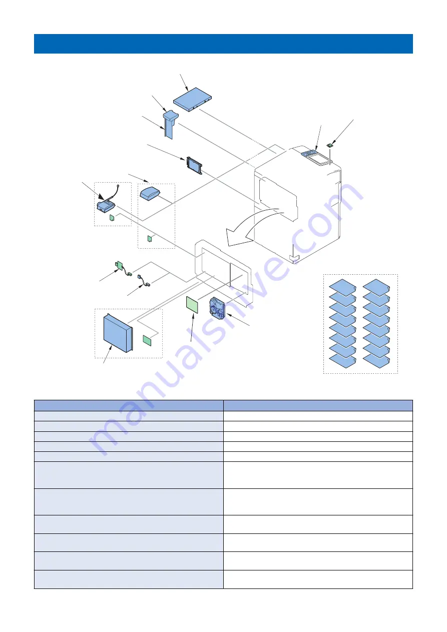
Function expansion system options
Numeric Keypad-A2
Licence option
Connection Kit-A4
for Bluetooth LE
Utility Tray-B1
Memory Mirroring Kit-A1
Super G3 FAX Board-AX1
Super G3 2nd Line Fax Board-AX1
Copy Control Interface Kit-A1
Serial Interface Kit-K3
imagePRESS Server M20
Voice Guidance Kit-G1
Voice Operation Kit-D1
250GB SSD-A1
1TB SSD-A1
Copy Card Reader-F1
Copy Card Reader Attachment-A5
Hardware product
Product name
Required options, conditions, etc.
“ Connection Kit-A4 for Bluetooth LE” on page 189
“Numeric Keypad-A2” on page 205
“Super G3 FAX Board-AX1” on page 264
“Super G3 2nd Line Fax Board-AX1” on page 272
Super G3 FAX Board-AX1 is required.
“imagePRESS Server M20” on page 301
(imagePRESS Server M20)
“Serial Interface Kit-K3/Copy Control Interface Kit-A1” on page
257
Required when the coin manager is connected.
Using with Copy Card Reader-F1 and Serial Interface Kit-K3 is not
available.
“Serial Interface Kit-K3/Copy Control Interface Kit-A1” on page
257
Required when the coin manager is connected.
Using with Copy Card Reader-F1 and Copy Control Interface Kit-
A1 is not available.
“Voice Guidance Kit-G1” on page 235
Cannot be installed with Utility Tray-B1.
Cannot be installed with Voice Guidance Kit-D1.
“Voice Operation Kit-D1” on page 246
Cannot be installed with Utility Tray-B1.
Cannot be installed with Voice Guidance Kit-G1.
“SSD-related Option” on page 282
It is required when using the mirroring function with Memory Mir-
roring Kit-A1.
“SSD-related Option” on page 282
It is required when using the mirroring function with Memory Mir-
roring Kit-A1.
1. Product Lineup
8
Summary of Contents for imagePRESS Lite C270
Page 10: ...Safety Precautions Toner Safety 2 Points to Note at Installation 2 ...
Page 34: ...1 Open the ADF 2 2 Host Machine 25 ...
Page 38: ...9 Store the Scanner Fixation Member 10 Store the Scanner Fixation Member 2 Host Machine 29 ...
Page 39: ...11 Install the Maintenance Cover Upper 12 2 Host Machine 30 ...
Page 141: ... Adjustment of the White Plate 1 2 Host Machine 132 ...
Page 152: ...2 3 2 Host Machine 143 ...
Page 156: ...9 10 11 2 Host Machine 147 ...
Page 157: ...12 Connect the power plug to the outlet 13 Turn ON the main power switch 2 Host Machine 148 ...
Page 158: ...Image Reading System Options 3 Printer Cover H2 150 Reader Heater P1 169 ...
Page 161: ...2 2x 3 4 1x 3 Image Reading System Options 152 ...
Page 162: ...5 3x 3 Image Reading System Options 153 ...
Page 163: ... Removing the ADF 1 1x 2x 3 Image Reading System Options 154 ...
Page 166: ...5 3x 6 3 Image Reading System Options 157 ...
Page 167: ...7 CAUTION Be careful not to drop the ADF 4x 3 Image Reading System Options 158 ...
Page 168: ... Removing the Reader Unit 1 3x 2 2x 2x 3 Image Reading System Options 159 ...
Page 169: ...3 3x 4 4x 3 Image Reading System Options 160 ...
Page 176: ... Installing the Covers 1 3x 2 1x 3 2x 3 Image Reading System Options 167 ...
Page 182: ...5 6 3x 1x 3 Image Reading System Options 173 ...
Page 183: ...7 1x 8 3x 3 Image Reading System Options 174 ...
Page 184: ...9 10 11 2x 3 Image Reading System Options 175 ...
Page 185: ...12 13 Middle 3 Image Reading System Options 176 ...
Page 186: ...14 15 2x Binding M4x4 3 Image Reading System Options 177 ...
Page 187: ...16 Small 17 1x 3 Image Reading System Options 178 ...
Page 188: ...18 7x 19 2x 3 Image Reading System Options 179 ...
Page 189: ...20 21 3x 1x 3 Image Reading System Options 180 ...
Page 193: ...25 26 3x 3 Image Reading System Options 184 ...
Page 194: ...27 1x 1x 28 29 1x 3 Image Reading System Options 185 ...
Page 199: ...Installation Procedure 1 2 4 Host Machine Options 190 ...
Page 200: ...3 4 5x 4 Host Machine Options 191 ...
Page 202: ...7 3x 8 2x 9 4 Host Machine Options 193 ...
Page 208: ...17 1x 1x 12x 18 3x 4 Host Machine Options 199 ...
Page 209: ...19 1x 20 2x 21 4 Host Machine Options 200 ...
Page 210: ...22 6x 23 5x 24 4 Host Machine Options 201 ...
Page 211: ...25 26 4 Host Machine Options 202 ...
Page 212: ...27 4 Host Machine Options 203 ...
Page 215: ...Installation Procedure 1 2 4 Host Machine Options 206 ...
Page 216: ...3 4 5 4 Host Machine Options 207 ...
Page 219: ...10 3x 1x 11 Large 4 Host Machine Options 210 ...
Page 220: ...12 1x 1x 4 Host Machine Options 211 ...
Page 225: ...2 2x 4 Host Machine Options 216 ...
Page 226: ...3 CAUTION To avoid damage do not pull the Utility Tray too much 4 Host Machine Options 217 ...
Page 229: ...8 2x 2x TP M4x10 9 4 Host Machine Options 220 ...
Page 230: ... When Installing the USB Keyboard 4 Host Machine Options 221 ...
Page 233: ...Installation Procedure 1 16x 4 Host Machine Options 224 ...
Page 234: ...2 NOTE 2x NOTE Removed Screw will be used in step 6 3 1x 4 Host Machine Options 225 ...
Page 235: ...4 4 Host Machine Options 226 ...
Page 237: ...7 16x 4 Host Machine Options 228 ...
Page 238: ...8 4 Host Machine Options 229 ...
Page 239: ...9 10 1x Binding M4x20 4 Host Machine Options 230 ...
Page 245: ...Installation Outline Drawing 4 Host Machine Options 236 ...
Page 246: ...Installation Procedure 1 16x 4 Host Machine Options 237 ...
Page 247: ...2 2x NOTE NOTE Removed Screw will be used in step 3 4 Host Machine Options 238 ...
Page 248: ...3 NOTE Use the screws removed in step 2 TP M3x6 NOTE 1x 2x 2x 1x 4 Host Machine Options 239 ...
Page 249: ...4 CAUTION When cutting off the part be sure not to make burrs 4 Host Machine Options 240 ...
Page 250: ...5 16x 6 4 Host Machine Options 241 ...
Page 251: ...7 2x Binding M4x20 8 1x Binding M4x6 4 Host Machine Options 242 ...
Page 253: ...10 11 1x 1x 4 Host Machine Options 244 ...
Page 256: ...Installation Outline Drawing 4 Host Machine Options 247 ...
Page 257: ...Installation Procedure 1 16x 4 Host Machine Options 248 ...
Page 258: ...2 2x NOTE NOTE Removed Screw will be used in step 3 4 Host Machine Options 249 ...
Page 259: ...3 NOTE Use the screws removed in step 2 TP M3x6 NOTE 1x 3x 1x 1x 4 Host Machine Options 250 ...
Page 260: ...4 CAUTION When cutting off the part be sure not to make burrs 4 Host Machine Options 251 ...
Page 261: ...5 16x 4 Host Machine Options 252 ...
Page 262: ...6 7 2x Binding M4x20 4 Host Machine Options 253 ...
Page 263: ...8 4 Host Machine Options 254 ...
Page 268: ...Copy Control Interface Kit A1 Installation Procedure 1 16x 4 Host Machine Options 259 ...
Page 269: ...2 2x 4 Host Machine Options 260 ...
Page 270: ...3 Serial Interface Kit K3 1x 4 Host Machine Options 261 ...
Page 271: ...Copy Control Interface Kit A1 1x 4 Host Machine Options 262 ...
Page 276: ...2 1x 1x 1x 1x 1x TP M3x6 3 Install the removed cover 4 Host Machine Options 267 ...
Page 282: ...Installation Outline Drawing 4 Host Machine Options 273 ...
Page 286: ...3 4x W Sems M3x8 4 Host Machine Options 277 ...
Page 287: ...4 9 7 mm 22 mm 6x 4x 4 Host Machine Options 278 ...
Page 288: ...5 5x 2x 6 3x 2x 7 Install the removed cover and telephone cord 4 Host Machine Options 279 ...
Page 293: ...1 16x 4 Host Machine Options 284 ...
Page 294: ...2 4 Host Machine Options 285 ...
Page 297: ...6 4 Host Machine Options 288 ...
Page 302: ...1 16x 4 Host Machine Options 293 ...
Page 303: ...2 1x 4 Host Machine Options 294 ...
Page 305: ...5 4 Host Machine Options 296 ...
Page 306: ...6 1x 4 Host Machine Options 297 ...
Page 307: ...7 1x 2x 4x 4 Host Machine Options 298 ...
Page 312: ...2 NOTE If screws and a face cover are attached remove them 4 Host Machine Options 303 ...
Page 314: ...5 8x 4 Host Machine Options 305 ...
Page 316: ...7 4x 8x 4 Host Machine Options 307 ...
Page 317: ...8 Toothed Washer Screw Binding M4x8 4x 4 Host Machine Options 308 ...
Page 318: ...9 4x 4 Host Machine Options 309 ...
Page 327: ...Installation Procedure 1 6x 2 3x 4 Host Machine Options 318 ...
Page 328: ...3 1x 4 4x 4x 4 Host Machine Options 319 ...
Page 329: ...5 2x M3x6 6 4 Host Machine Options 320 ...
Page 331: ...9 3x 10 4x 4 Host Machine Options 322 ...
Page 333: ...13 2x 4 Host Machine Options 324 ...
Page 341: ...14 Install the Connector 1x 15 Install the Connector Cover 5 Paper Feed Options 332 ...
Page 360: ...4 Fasten the 2 screws loosened at procedure 3 2 Screws 2x Fasten 5 Paper Feed Options 351 ...
Page 422: ...8 Pull out the 2 Slope Plates from the palette 9 Remove the 2 Pins 5 Paper Feed Options 413 ...
Page 487: ...14 Close the Deck Left Front Cover 5 Paper Feed Options 478 ...
Page 501: ...11 Open the Wire Saddle of the Through Pass Unit 5 Paper Feed Options 492 ...
Page 533: ...2 5 Paper Feed Options 524 ...
Page 535: ...4 5 Paper Feed Options 526 ...
Page 537: ...5 Paper Feed Options 528 ...
Page 551: ...12 5 CAUTION Be sure that it is not placed on the boss 1x 12 6 12 7 5 Paper Feed Options 542 ...
Page 744: ... Installing the Finisher Long Sheet Catch Tray 1 2 6 Paper Output Options 735 ...
Page 755: ...7 Remove the Rear Cover 2 Screws Loosen 6 Screws 6x 2x 6 Paper Output Options 746 ...
Page 779: ... Connecting to the Host Machine 1 4x Binding M4x8 2 1x 1x 6 Paper Output Options 770 ...
Page 784: ...2 3 TP M3x6 1x 6 Paper Output Options 775 ...
Page 785: ...4 Pull out the saddle unit Booklet Finisher only 6 Paper Output Options 776 ...
Page 799: ...6 7 1 5 mm 10 1 1 5 mm 6 Paper Output Options 790 ...
Page 801: ...2 Remove the Caster Covers Front Rear 6 Paper Output Options 792 ...
Page 821: ...12 Affix the Face Seal to the Punch Unit 6 Paper Output Options 812 ...
Page 838: ...2 1x TP M3x6 R L 1x 3 2x TP M3x6 F 2x 6 Paper Output Options 829 ...
Page 839: ...4 Place the Jogger Kit on Finisher 5 3x TP M3x6 3x 6 Paper Output Options 830 ...
Page 840: ...6 7 1x 6 Paper Output Options 831 ...
Page 841: ...8 2x 9 1x 6 Paper Output Options 832 ...
Page 857: ...6 Paper Output Options 848 ...
Page 878: ...2x 9 Connect the 3 connectors 3x 10 Open the Slide Cover 6 Paper Output Options 869 ...


