

COPYRIGHT © 1999 CANON INC.
CANON DADF-B1 REV.0 APR. 1999 PRINTED IN JAPAN (IMPRIME AU JAPON)
5-15
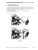
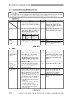
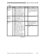
CHAPTER 5 TROUBLESHOOTING
IV. VARIABLE RESISTORS (VR), LIGHT-EMITTING
DIODES, AND CHECK PINS BY PCB
Of the variable resistors (VR), light-
emitting diodes (LED), and check pins used in
the machine, those needed for servicing in the
field are discussed.
Caution:
Do not touch those VRs and check pins
not discussed herein. They are for the
factory, and require especial instruments
and high accuracy.
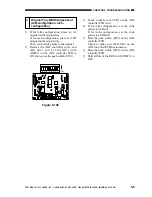
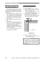
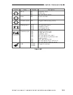
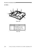
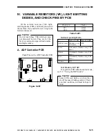
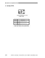
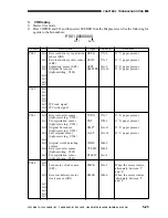
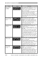
A. ADF Controller PCB
· Check Pins on the ADF Controller PCB
Figure 5-401
Table 5-401
·
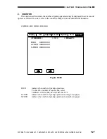
Normal Operating Mode
·
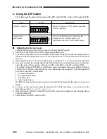
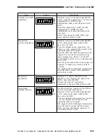
Test Mode by DIP SW
For a guide to LED indication in test mode,
see V.C. "Using the DIP Switch."
Caution:
Some LEDs emit light even when they
are off because of leakage current. This is
a normal condition, and must be kept in
mind.
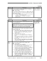
Check pin
Checks
CP1
GND
CP17
GND
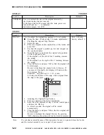
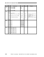
State of LED
State of LED2
ADF at reset Flashes every OFF
100 msec
Error
Alternately flashes every 150
msec
Alarm
Alternately flashes every 800
msec
Jam
Alternately flashes every 400
msec
Others
Off
DSW1
SW1
CP17
LED2
LED1
J10
J5
J9
J2
J1
J7
J6
CP1


