background image

30

The section describes how to use x2 photography, small pupil photography function, diopter 
compensation, and anterior eye photography and how to connect an external monitor when one is 
used. 

x2 Photography

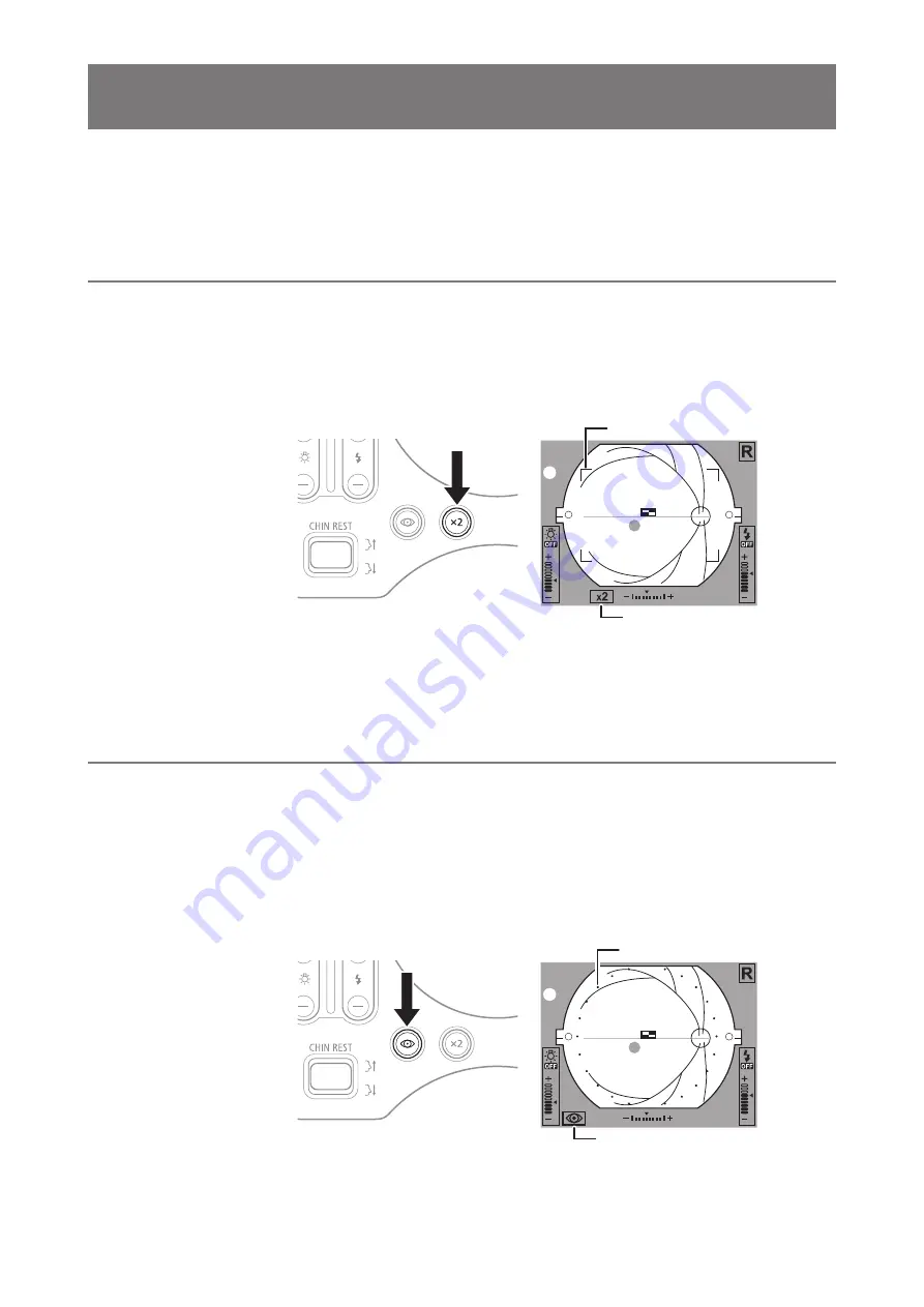
You can take and save images that are within the x2 photography range on the observation monitor. 

Press the x2 photography button. 

The lamp on the x2 photography button lights, and the x2 photography indicator and x2 photography 
range marks appear on the observation monitor. 

x2 photography 

indicator

x2 photography 

range mark 

Take the image. 

The image in the x2 photography range appears on the Rics NM 2 screen. 

Small Pupil Photography Function

If the diameter of the patient’s pupil is smaller than the inner pupil alignment circle after waiting for 
a while in a dark room, use the small pupil photography function. When the function is used, pupil 
diameters 3.3 mm or larger can be photographed. 

Press the small pupil photography button. 

The lamp on the small pupil photography button lights, and the small pupil photography indicator and 
a dotted circle appear on the observation monitor. 

Small pupil 

photography indicator

Effective range of 

photography 

5

 Photography Auxiliary Functions

Summary of Contents for CR-2

Page 1: ...Digital Retinal Camera Operation Manual Make sure you read this manual before using the instrument Keep this manual safely so that you can use it in the future ...

Page 2: ... image data regardless of the cause of the loss of the image data Canon takes no responsibility for injuries or property damage that may occur if safety precautions are not followed or the instrument is used for something other than its intended purpose Medical examinations are the responsibility of a doctor Canon takes no responsibility for diagnostic results Follow the laws relating to the produ...

Page 3: ...4 Alignment 25 Photography 28 Finishing an Examination 29 5 Photography Auxiliary Functions 30 x2 Photography 30 Small Pupil Photography Function 30 Diopter Compensation 31 Anterior Eye Photography 32 External Monitor 32 6 Maintenance 34 Maintenance and Inspection 34 Cleaning the Objective Lens 35 Cleaning the Image Sensor 36 Cleaning the Outside of the CR 2 36 Disinfecting the Forehead Rest 37 Re...

Page 4: ...tal camera The CR 2 is equipped with a special digital camera using EOS digital technology This enables the CR 2 to fully maximize Canon technology for shooting high quality high resolution diagnostic images Small pupil photography function The CR 2 take retinal images through pupils of the normal diameters from 4 0 mm When using the small pupil photography function it can take through pupils of t...

Page 5: ...objective lens Dust cover Use it to cover the CR 2 when it s not being used Body cap Initially covers the mount on the digital camera Operation Manual for the CR 2 this document Describes the handling precautions and operating instructions for the CR 2 CD ROM Retinal imaging control software NM 2 Contains the Retinal imaging control software NM 2 Rics NM 2 which is used to record view and store ph...

Page 6: ...h or serious injury CAUTION A caution that incorrect operation may result in serious injury CAUTION A caution that incorrect operation may break the CR 2 or damage other devices This symbol indicates things that must not be done prohibited actions This symbol indicates things that must be done This symbol indicates important advice that we strongly recommend be followed while operating the CR 2 Th...

Page 7: ...988 A1 1991 A2 1995 Medical electrical equipment Part 1 General requirements for safety IEC 60601 1 1 Ed 2 0 2000 Medical electrical equipment Part 1 1 General requirements for safety Collateral standard Safety requirements for medical electrical systems IEC 60601 1 2 Ed 2 1 2004 Medical electrical equipment Part 1 2 Collateral standard Electromagnetic compatibility Requirements and tests IEC 6060...

Page 8: ... Software life cycle processes EN 62366 2008 Medical device Application of usability engineering to medical devices EN ISO 14971 2007 Medical device Application of risk management to medical devices EN ISO 15004 1 2006 Ophthalmic instruments Part 1 General requirements applicable to all ophthalmic instruments EN ISO 15004 2 2007 Ophthalmic instruments Part 2 Light hazard protection EN ISO 10993 1 ...

Page 9: ...not place near to a flammable solvent Fire may result if the solvent spills or evaporates and makes contact with internal electric parts Some disinfectants are flammable Be sure to take care when using them Stop using immediately if there is an abnormality or problem If an abnormality occurs immediately unplug the power plug and turn off the power of all the devices Smoke is emitted An unusual sme...

Page 10: ...t or cables for safety reasons be sure to turn off the power of all the devices Otherwise it may result in electric shock Prohibited Do not play the supplied CD ROM in any CD Player unsupporting data CD ROMs Playing the CD ROM in an audio CD player may damage the speaker It is also possible to suffer hearing loss from listening with headphones to the loud sounds of the CD ROM on an audio CD player...

Page 11: ... Digital Retinal Camera CR 2 Be sure that the entire system conform to IEC 60601 1 1 Be sure to also use an isolation transformer conforming to IEC 60601 1 when a computer or monitor conforming to IEC 60950 1 is used Otherwise it may result in electric shock For details please contact a Canon representative or distributor Keep the forehead rest and chin rest clean To prevent the risk of infection ...

Page 12: ...ove to the center position when the CR 2 main unit is turned on or a study is finished with the control software Do not touch the main unit and the chin rest while they are moving At the same time keep the patient s chin away from the chin rest Before packing the CR 2 return the main unit and chin rest to their initial positions Lower the main unit and chin rest to the bottom To automatically lowe...

Page 13: ... the retinal camera If any dirt fingerprints dust or other foreign object is on the lens or mirror you cannot take a good image After use After using the CR 2 turn off the power cover the objective lens with the objective lens cover to protect it from dust and place the dust cover over the CR 2 You cannot take good images if the objective lens is dusty If the digital camera is detached and left un...

Page 14: ...h the objective lens cap and place the dust cover over the CR 2 Installation Ask the Canon representative or distributor from whom you purchased the CR 2 to install it A strong shock to the CR 2 may put it out of alignment Please handle it carefully Transportation Lower the main unit and chin rest to the bottom To automatically lower them turn on the power while holding down the set button Be sure...

Page 15: ...trical and electronic equipment EEE Improper handling of this type of waste could have a possible negative impact on the environment and human health due to potentially hazardous substances that are generally associated with EEE At the same time your cooperation in the correct disposal of this product will contribute to the effective usage of natural resources For more information about where you ...

Page 16: ...ations in the European Union Product that WEEE directive Directive on Waste Electrical and Electronic Equipment 2002 96 EC requires separate collection The directive is effective in the European Union only Certification mark that indicates the product complies with UL 60601 1 and CAN CSA 22 2 No 601 1 that specifies protection against fire electric shock and mechanical hazards Caution Grounding re...

Page 17: ...hutter release button 7 Alignment button Switches between a view of the anterior eye and the retina 8 Main unit vertical movement ring Turn right Main unit moves up Turn left Main unit moves down 9 Focus ring Turn to focus the image 10 Stage lock 11 Indentation for lifting 12 Height adjustment mark 13 Main unit 14 Operation panel 15 USB connector 16 AC power connector 17 Power switch for main unit...

Page 18: ... Connector for the external eye fixation lamp sold separately 20 Forehead rest 21 Objective lens 22 Objective lens cap 23 Face rest 24 Chin rest 25 Indentation for lifting 26 Diopter compensation knob a No diopter compensation b Negative compensation c Positive compensation d Anterior eye photography 27 Base ...

Page 19: ...ght brightness decreases 3 x2 photography button lamp Enables x2 photography function See page 30 4 Small pupil photography button lamp Enables small pupil photography function See page 30 5 CHIN REST button Top Raises chin rest Bottom Lowers chin rest 6 FIX TARGET button Move up down right and left to move internal eye fixation lamp 7 Set button lamp Internal eye fixation lamp blinks 8 POWER lamp...

Page 20: ...or eye photography 6 Flash intensity indicator 1 Indicator for top limit of position of main unit Appears when main unit has reached top limit 2 Focus indicator 3 WD guide green 4 Indicator for bottom limit of position of main unit Appears when main unit has reached bottom limit 5 x2 photography indicator 6 Small pupil photography indicator 7 x2 photography range 8 Diopter compensation knob positi...

Page 21: ... as described in Connecting Cables see page 22 Preparing for an examination page 22 Setup for patient page 24 Alignment page 25 Small pupil photography page 30 x2 photography page 30 Diopter compensation page 31 Anterior eye photography page 32 Photography page 28 Finishing an examination page 29 4Basic Operations ...

Page 22: ...n AC outlet 4 Connect the other end of the USB cable to the USB connector of the PC Use a high speed AB type USB cable that is 3 meters or shorter For details contact the Canon representative or distributor from whom you purchased the CR 2 Preparing for an Examination CAUTION To prevent the risk of infection wipe the forehead rest with ethanol solution or any other disinfectant whenever changing p...

Page 23: ...in away from the chin rest Power saving function If the power is on and the buttons on the operation panel are not operated for over 10 minutes the power saving function is activated The POWER lamp blinks while in power saving mode To return to normal mode press any button on the operation panel move the stage right or left or turn the diopter compensation knob 4 Make sure the diopter compensation...

Page 24: ...on the patient Instruct the patient to remove their contact lenses or glasses if they are wearing them Have the patient place their chin on the chin rest and their forehead against the forehead rest Adjust the heights of the optical bench and chair so the patient is comfortable 3 Move the chin rest with the CHIN REST button so that the patient s eye is aligned with the height adjustment mark Chin ...

Page 25: ... circles 3 Have the patient stare at the green blinking internal eye fixation lamp Pupil alignment circles When examining the anterior eye of a patient who is extremely near or far sighted the patient may not be able to see the internal eye fixation lamp To move the main unit slightly to the left or right tilt the operation lever to the left or right To move the main unit slightly to the front or ...

Page 26: ... function see page 30 3 Press the alignment button The retina appears in the observation monitor and the internal eye fixation lamp blinks for three seconds 4 Adjust the observation light brightness with the observation light brightness button Guidelines for observation light brightness Adjust to the lowest possible brightness level to reduce the strain on the patient s eye Observation monitor bri...

Page 27: ...ernal eye fixation lamp sold separately Set button Press the set button for over two seconds to reset the position of the internal eye fixation lamp See the Rics NM 2 manual for details 6 Turn the focus ring to align the split lines into a single line The image enlarges while the focus ring is being turned Focus ring Split line Correct Incorrect Incorrect When the split lines do not align If the p...

Page 28: ...en None Cannot access the Rics NM 2 The retina observation mode is not established Flash intensity adjustment The flash intensity is set to the standard level in advance Every time the flash intensity button is pressed the flash intensity increases by 0 3 stop 2 Press the shutter release button The image of the retina and the examination information appear on the Rics NM 2 screen 3 Check the photo...

Page 29: ...e chin rest moves to the center position when a study is finished with the control software Do not touch the main unit and the chin rest while they are moving 2 Align the stage with the base and slide the stage lock to LOCK side to lock the stage Align the mark on the stage lock and the mark on the right side of the base 3 Turn off the power to the CR 2 4 Exit the Rics NM 2 and turn off the comput...

Page 30: ...indicator x2 photography range mark 2 Take the image The image in the x2 photography range appears on the Rics NM 2 screen Small Pupil Photography Function If the diameter of the patient s pupil is smaller than the inner pupil alignment circle after waiting for a while in a dark room use the small pupil photography function When the function is used pupil diameters 3 3 mm or larger can be photogra...

Page 31: ...ge the position Insert the diopter compensation lens into the CR 2 and take the photograph 0 Negative Positive Diopter compensation mark The CR 2 can provide appropriate images if the diopter of the patient s eye fall within each range below 0 position 10 to 15 D position 31 to 7 D position 11 to 33 D Note that when the diopter compensation knob is set to the or position the focus indicator does n...

Page 32: ...an be seen as clearly as possible Make sure that the photography ready lamp lights green 4 Press the shutter release button The image of the retina appears on the Rics NM 2 screen To take images of another position repeat steps from step 2 External Monitor The image on the observation monitor can be viewed on an external monitor Contact the Canon representative or distributor from whom you purchas...

Page 33: ...ook onto the strap mount of the digital camera 2 While taking care to avoid pinching the video cable insert the cover screw to secure the digital camera cover Cover screw 4 Connect the video cable to the external monitor Connect the video cable to the video input terminal yellow on the external monitor Turn on the external monitor and select the input using the monitor s input switch Audio Video i...

Page 34: ...ain unit 1 The digital camera cover and parts are not damaged or loose 2 The stage moves smoothly when the operation lever is tilted back and forth and right to left 3 The digital camera is securely installed 4 The stage lock operates properly 5 There are no scratches or dirt on the objective lens Clean the objective lens if it is dirty see page 35 Checks after turning on the power Turn on the CR ...

Page 35: ...e lens is dirty clean it according to the procedure below 1 Check for any dirt Illuminate the objective lens with a penlight to check for dirt 2 Blow away any dust or dirt Use a blower to blow away any dust or dirt on the lens Do not use a brush to dust off Do not allow the blower to touch the objective lens 3 Wipe the objective lens 1 Slightly dampen a lens cleaning paper with lens cleaner and li...

Page 36: ... and dust have been removed 4 Switch the digital camera s power switch to on photograph an image and check the image If the above procedure does not remove the foreign object the cause may not be dirt or dust Contact the Canon representative or distributor from whom you purchased the CR 2 Cleaning the Outside of the CR 2 WARNING Before cleaning the CR 2 be sure to turn off the power of all the dev...

Page 37: ... paper to the chin rest with the pins pressing into the holes on the chin rest Chin rest paper is a consumable product sold separately To purchase chin rest paper contact the Canon representative or distributor from whom you purchased the CR 2 Attaching and Removing the Digital Camera The CR 2 is equipped with a specialized digital camera It is not necessary to attach or remove the digital camera ...

Page 38: ...gital terminal and the remote control terminal 4 Remove the DC coupler 1 Open the battery compartment cover on the digital camera and then slide the battery lock lever to remove the DC coupler 2 Close the battery compartment cover 5 While holding down the lens release button on the digital camera turn the digital camera counterclockwise to remove it 6 Attach the caps to the retinal camera and the ...

Page 39: ...digital camera clockwise until it clicks Mounting alignment mark 3 Attach the DC coupler to the digital camera 1 Open the battery compartment cover of the digital camera and attach the DC coupler 2 Pass the cord for the DC coupler through the DC coupler cord hole and then close the battery compartment cover 4 Open the terminal cover of the digital camera and attach the cables to the digital termin...

Page 40: ...monitor does not turn on Turn on the digital camera An error appears Err xx on the observation monitor A malfunction has been detected in the digital camera Turn off the power to the retinal camera and then turn it on again The working distance dots are hard to see The observation light is too bright Reduce the observation light brightness The split lines are hard to see The working distance dots ...

Page 41: ...ter and small pupil photography function The objective lens is dirty Clean the objective lens see page 35 The patient is wearing contact lenses Instruct the patient to remove their contact lenses Black spots or any artifacts appear in the same place in every captured image There is dirt or dust on the objective lens Clean the objective lens see page 35 Dirt or dust is stuck to the imaging sensor o...

Page 42: ...line alignment type focusing Flash intensity Linked to the photography mode Can be set manually Light source Observation light source Infrared LED Flash source White LED Camera Digital camera Eye fixation lamp Internal eye fixation lamp LED External eye fixation lamp sold separately Range of motion Stage 100 mm side to side 70 mm front to back Main unit vertical movement 32 mm Chin rest range of m...

Page 43: ...magnetic Environment Guidance RF emissions CISPR11 GROUP 1 The CR 2 uses RF energy only for its internal function Therefore its RF emissions are very low and are not likely to cause any interference in nearby electromagnetic equipment RF emissions CISPR11 Class B The CR 2 is suitable for use in all establishments including domestic establishments and those directly connected to the public low volt...

Page 44: ... 5 1 kV differential mode 2 kV common mode 1 kV differential mode 2 kV common mode Mains power quality should be that of a typical commercial or hospital environment Voltage dips short interruptions and voltage variations on power supply input lines IEC 61000 4 11 5 UT 95 dip in UT for 0 5 cycles 40 UT 60 dip in UT for 5 cycles 70 UT 30 dip in UT for 25 cycles 5 UT 95 dip in UT for 5 sec 5 UT 95 d...

Page 45: ...ed RF transmitters as determined by an electromagnetic site surveya should be less than the compliance level in each frequency rangeb Interference may occur in the vicinity of equipment marked with the following symbol NOTE 1 At 80 MHz and 800 MHz the higher frequency range applies NOTE 2 These guidelines may not apply in all situations Electromagnetic propagation is affected by absorption and ref...

Page 46: ... distance d in metres m can be estimated using the equation applicable to the frequency of the transmitter where P is the maximum output power rating of the transmitter in watts W according to the transmitter manufacturer NOTE 1 At 80 MHz and 800 MHz the separation distance for the higher frequency range applies NOTE 2 These guidelines may not apply in all situations Electromagnetic propagation is...

Page 47: ...on the rating label Description of malfunction Report as much detail as possible Time limit for supplying performance parts for repair Performance parts parts for repairs to maintain performance will be stocked for eight years after production of the CR 2 is discontinued Expendable parts replaced by service personnel The following parts are consumable or may deteriorate because of characteristics ...

Page 48: ...N V Medical Products Division Bovenkerkerweg 59 61 1185 XB Amstelveen The Netherlands Telephone 31 20 545 8926 CANON SINGAPORE PTE LTD Medical Equipment Products Division 1 HarbourFront Avenue 04 01 Keppel Bay Tower Singapore 098632 Telephone 65 6799 8888 CANON AUSTRALIA PTY LTD Optical Products Division 1 Thomas Holt Drive North Ryde Sydney N S W 2113 Australia Telephone 61 2 9805 2000 L IE 5176 ...

Reviews: