CHAPTER 2
2 - 6
COPYRIGHT
2000 CANON INC. CANOSCAN N650U/N656U/N1220U REV.0 JUNE 2000 PRINTED IN JAPAN (IMPRIME AU JAPON)
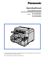
Figure 2-5
When the hardware setting, home position detection and border detection between black
and white have completed, the scanner is on standby to wait for a command from the host
computer.
Document glass (rear side)
White mark area
Black mark area
When the scanner is powered ON, it performs hardware setting, home position detection, and
border detection between black and white according to the flowchart shown in Figure 2-4.
1) Hardware setting
Gate array and buffer RAM in the main PCB are checked if they function normally.
2) Home position detection/Border detection between black and white
The scanner detects the home position by the home position sensor by using a black mark
area and white mark area in the rear of the document glass.
Firstly the home position sensor defines the home position, where the scanning unit reads a
black mark area.
Secondly, the border between a white mark area and black mark area is detected. The
scanning unit moves forward reading image signals with the LED of the contact image sensor
turned ON. When the scanning unit has reached the white mark area, and the peak value of the
light intensity to the scanning unit has reached a white level, the scanning unit stops to define
there as the border between a black mark area and white mark area. The number of steps of the
drive motor is calculated to define the distance from the home position to the white mark area.