


COPYRIGHT © 2000 CANON INC.
COPYRIGHT © 2000 CANON INC. 2000 2000 2000 2000
2000 2000 2000 2000
CANON NW Multi-PDL P. kit-A1 REV.0 SEPT. 2000 PRINTED IN USA
CANON NW Multi-PDL P. kit-A1 REV.0 SEPT. 2000 PRINTED IN USA
CHAPTER 2 OPERATIONS
CHAPTER 2 OPERATIONS
2-6
2-6
2.2.2
2.2.2 Pr
Proc
oces
essi
sing b
ng by th
y the Pr
e Prin
inte
terr
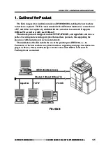
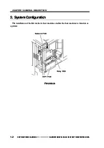
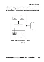
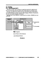
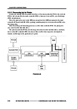
A print job coming from the parallel interface of the main controller PCB or the network
A print job coming from the parallel interface of the main controller PCB or the network
PCB is first checked by the main controller PCB to find out if it is in PCL or in PostScript
PCB is first checked by the main controller PCB to find out if it is in PCL or in PostScript
(PDL
(PDL identif
identification).
ication).
Then, the print job is sent to the RIP processing block for RIP processing by the main
Then, the print job is sent to the RIP processing block for RIP processing by the main
controller PCB and the RIP1 PCB operating simultaneously for conversion from PDL data
controller PCB and the RIP1 PCB operating simultaneously for conversion from PDL data
into image data.
into image data.
After smoothing and thickening processes on the main controller PCB, the print job is
After smoothing and thickening processes on the main controller PCB, the print job is
once stored on the hard disk drive.
once stored on the hard disk drive.
The system controller PCB reads the image data stored on the hard disk drive, and trans-
The system controller PCB reads the image data stored on the hard disk drive, and trans-
fers it to the DC controller PCB; the data is then used for laser exposure, development,
fers it to the DC controller PCB; the data is then used for laser exposure, development,
transfer, and fixing for the generation of a print.
transfer, and fixing for the generation of a print.
F02-202-02
F02-202-02
Print job
Print job
Print job
Print job
RIP
RIP
processing
processing
RIP1
RIP1
PCB
PCB
Parallel
Parallel
interface
interface
Smoothing/
Smoothing/
thickening
thickening
Network PCB
Network PCB
PDL
PDL
identification
identification
D
D
C
C
C
C
o
o
n
n
t
t
r
r
o
o
l
l
l
l
e
e
r
r
P
P
C
C
B
B
HDD
HDD


