


COPYRIGHT © 2000 CANON I
COPYRIGHT © 2000 CANON INC.
NC. 2000 2000 2000 2000
2000 2000 2000 2000
CANON NW Multi-PDL P. kit-A1 REV.0 SEPT. 2000 PRINTED IN USA
CANON NW Multi-PDL P. kit-A1 REV.0 SEPT. 2000 PRINTED IN USA
CHAPTER 1 GENERAL DESCRIPTION
CHAPTER 1 GENERAL DESCRIPTION
1-5
1-5
5.
5. O
Op
pe
erra
attiio
on
n
5.
5.1
1 O
Ou
uttlliin
ne
e
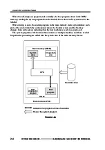
You can check the progress of a print job by selecting the system status indicator found in
You can check the progress of a print job by selecting the system status indicator found in
the right bottom of the screen and then selecting the print tag on the pop-up screen.
the right bottom of the screen and then selecting the print tag on the pop-up screen.
The network settings and various print settings are made in user mode.
The network settings and various print settings are made in user mode.
5.2
5.2 S
Se
ettttiin
ng
gs
s
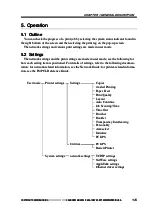
The network settings and the print settings are made in user mode; see the following for
The network settings and the print settings are made in user mode; see the following for
how each setting item is positioned. For details of settings, refer to the following documen-
how each setting item is positioned. For details of settings, refer to the following documen-
tation: for network-related information, see the Network Guide; for
tation: for network-related information, see the Network Guide; for printer-related informa
printer-related informa--
tion, see the PS/PCL Reference Guide.
tion, see the PS/PCL Reference Guide.
U
Usseer
r
m
mo
od
dee
C
Co
op
piieess
2-sided Printing
2-sided Printing
Paper Feed
Paper Feed
Print Quality
Print Quality
Layout
Layout
Auto Continue
Auto Continue
Job Securing Time
Job Securing Time
Time Out
Time Out
Finisher
Finisher
Booklet
Booklet
Transparency Interleaving
Transparency Interleaving
Personality
Personality
Autoselect
Autoselect
Initialize
Initialize
PCL/PS
PCL/PS
PCL/PS
PCL/PS
Restert Printer
Restert Printer
TCP/IP settings
TCP/IP settings
NetWare settings
NetWare settings
AppleTalk settings
AppleTalk settings
Ethernet driver settings
Ethernet driver settings
Settings
Settings
Utilities
Utilities
network settings
network settings
Printer settings
Printer settings
System settings
System settings


