background image

Summary of Contents for AE-1

Page 1: ...LE FINISHER AE2 PUNCHER UNIT LIIMIINIIPI INSTALLATION PROCEDURE Follow the instructionsherein when installingthe Productto its host machine 4 Z 3 5 1 3 UTD FJIR Z T T E b o PUB F IM 6673 000 PRINTED I...

Page 2: ...12 and then install them according to the following installation instructions When installing only the finisher see P 12 When installing the finisherand puncher unit at the same time see P 23 When in...

Page 3: ...y Unit A1 is installed The 3 Way Unit A1 comes in two types depending on the model either as standard equipment or as an option I Fixingplate 2 Fixing plate 5 Staple cartridge 7 Front foot cover 3 Fix...

Page 4: ...1 5 Stepped screw M4 2pcs 1 5 Stepped screw M4 1 6 Tray label 1 sheet 1 6 Tray label 1 7 Settings label 1 sheet 17 Settings label 18 Bookmaking label 19 Rear foot cover Buffer Pass Unit E2 I Buffer p...

Page 5: ...front lower cover fixingplate 1 1pc lo Steppedscrew M4X5 2 pcs 4 Punch front lower cover fixingplate 2 1pc l l11 Steppedscrew M4X10 2 pcs 5 Punch Jam Removal label 1PC 12 Screw binding M4X6 5 pcs 2 6...

Page 6: ...SaddleFinisher AE2 3 4 Puncherunit 4 5 Connectionto the host machine a Turning Off the Main Power of the Host Machine When turning off the main power be sure to go through the followingin strict sequ...

Page 7: ...ork e g removal of paper Be sure also that there will be no gap between the finisher and the host machine Finisher AEl 100 or more unit mm F 1 5 unit mm F 1 6 A Be sure to install the host machine and...

Page 8: ...2 driver 2 Detach the blanking part 3 using a flat blade screwdriver or the like 3 Remove the paper full sensor flag 4 for delivery tray 1 Do not remove the paper full sensor flag 5 for de livery tray...

Page 9: ...n its side you would likely deform or damage the machine Moreover in the case of the SaddleFinisher AE2 the force applied to the front cover l can deform the hinge The finisher is rather heavy Weight...

Page 10: ...he finisher 2 tray fixings 2 A For the Saddle Finisher AE2 do not peel off the blind seal I from the saddletray I F 1 12 8 In the case of the Finisher AEl openthe front door I In the case of the Saddl...

Page 11: ...isher AE2 1 Slide out the stitcher unit I to the front and re move the tape 2 Remove the screw I and remove the stitcherfix ing member 2 MEMO If the FoldingRolleris not used for a long time the releas...

Page 12: ...e removed us seven screws When Installing Only the Finisher 2 1 I Making Preparing on the Host Machine Before connecting the finisher to its host machine mount the fixing plate to the host machine 1 D...

Page 13: ...ingplate l and then attach the cover in place A Check to make sure that the host machine is off and its power plug is not connectedto the power outlet Dependingon the conditionof the floorof the site...

Page 14: ...the fixingplate Thefigureshowsa Sad dle Finisher AE2 Checkingthe heightltilt at the front 1 In the case of the Finisher AE1 openthe frontdoor I remove the three screws 2 and then detach the front cove...

Page 15: ...re move its auxiliary caster and rear foot cover Be sure to remove the auxiliary casterwith the finisher and the host machine intact in order to prevent the machine from tumbling over 1 If you need t...

Page 16: ...to decreasethe gapbetween the finisher and its host machine turn the adjusting bolt 2 in the direction of arrow A A full turn will increase the height of the finisherby 1 75mrn 3 If you want to incre...

Page 17: ...Mount the ground rail I to the finisher using two screws 2 binding M4 x 6 4 Attach the included rubber sheet I to the Buffer Pass Unit E2 along the line of reference 2 5 Mount the face plate I include...

Page 18: ...ing the interface cable be sure that the host machineis off and itspowerplug is discon nected from the power outlet Otherwise you can suffer an electric shock SaddleFinisher AE2 1 Separatethe finisher...

Page 19: ...ng M4 x 6 2 that comes with the Buffer Pass Unit E2 7 Open the front cover 8 Mount the front foot cover I using a screw 2 RS tightening M3 x 8 9 Mount the lower front extension cover 3 using a screw 2...

Page 20: ...the finisher 3 using a stepped screw 2 M4 The figure shows a SaddleFinisher AE2 14 Mount the rear upper cover small to the finisher using a screw 15 Connectthe finisherto the host machineusing the in...

Page 21: ...turn on the host machine and check the paper feed and stapleroperation A If a jam or malfunction occurs after checking nor mal operation follow the procedure explained in 2 6 Checking the HeighdTilt...

Page 22: ...epancyin height is 1 5mm or less 2 Check the tilt of the finisher and the host machine Check to see that the gap between the top edges of the finishertop cover and the host machinedelivery coveris 11...

Page 23: ...covers l and 2 fromthe left cover using a nipper 2 Detach the blanking cover 3 from the left rear cover using a nipper A When mounting the puncher unit mount the fix ing plate that comes with the pun...

Page 24: ...the shippingbox 2 Remove the tape from the outside of the puncher unit 3 Open the punch upper cover 4 Removethe two fixing screws l each and detach the front and rear punch fixingplates 2 3 1 3 Instal...

Page 25: ...of a Finisher AE1 thejoint would likely interfere Be sure to hook the puncher unit 2 in place while keeping the upper cover l of the fin isher open F 1 64 4 Using a long screwdriver secure the puncher...

Page 26: ...f the face cover 3 using nippers 8 Securelyfit the connectorcable of the puncher unit to the two connectorson the PCB of the finisher A Check to be sure that the connector is in firm con tact If the p...

Page 27: ...it with the rib 2 on the right side of the puncher unit and paste it on 10 Mount the finisher srear cover and the cable cov er 11 Mount the rear small cover of the finisher using a screw of the finish...

Page 28: ...and detach the rear Finisher AEl cover 2 of the puncher unit Saddie Finisher AE2 2 Fit the face cover I that comes with the unit 3 Connectthe host machine and the puncherunit and secureit inplace to t...

Page 29: ...wer front cover 2 in place using a screw 3 self tapping M4 x 12 3 self tapping M4 x 12 6 Mountthe punch lower front extensioncover 4 to the punch lower front coverusing a screw 5 self tapping M4 x 12...

Page 30: ...and bot Tilt tom index lines Check the height at both front and rear by referring to the two sets of index lines be surethat the discrepancyinheight is 1 5rnm or less 2 Check the tilt of the puncher...

Page 31: ...foot cover of the finisher before adjusting the height be sure to remove the auxiliaryring withoutdisconnectingthe finisherfrom its host machineto preventthe finish er from tumbling over Finisher AE1...

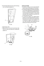
Page 32: ...while turning the bolt and perform this for both front and rear casters Adjusting the Tilt 1 Loosen the two fixing screws I each on the front and rear casters on the delivery side of the finisher 2 T...

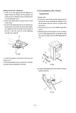
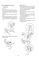
Page 33: ...affect the heighthilt 4 Attach the spanners to the back of the front cover using a screw 5 End the installation work as instructed in Installa tion after ChecksIAdjustments and later 3 2 2 Installati...

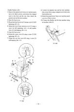
Page 34: ...extension cover 3 using a screw 4 RS tightening M3 x 8 and another screw 5 self tapping M4 x 12 5 Close the front cover 6 Mount the caster cover 6 using a screw 7 RS tightening M3 x 8 7 Mount the rear...

Page 35: ...ings labels 2 within the frames of the tray labels as usage 3 In the case of the Saddle Finisher AE2 attach the bookmaking label 3 to the saddletray as shown 3 3 2 Attaching the Label Puncher Unit 1 O...

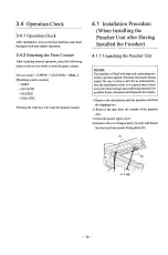
Page 36: ...Installing the Puncher Unit after Having Installed the Finisher 4 1 I Unpacking the Puncher Unit MEMO The machine is fittedwith tape and cushioning ma terial to protect againstvibration and shock dur...

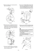
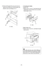
Page 37: ...pow er plug from the power outlet 2 Disconnect the interface cable l of the finisher from the host machine 3 In the case of a Finisher AEl remove the screw I and detach the lower front extensioncover...

Page 38: ...screw 4 anddetachthe rear footcover 5 Re move the screw 6 and detachthe caster cover 7 9 Remove the four screws l and detach the fixing plate front 2 and the other fixingplate rear 131 A If the fixing...

Page 39: ...crews I and detach the inlet guide 2 then remove the four screws 3 and de tach the right cover 4 Saddle Finisher AE2 1 Remove the two screws I and detach the right front cover 2 A If the rubber sheet...

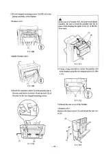
Page 40: ...mounting screws A In the case of a Finisher AE1 thejoint would likely interfere Be sure to hook the puncher unit 2 in place while keeping the upper cover I of the fin isher open 1 1I F 1 111 4 Using...

Page 41: ...er 6 Securelyfit the connectorcable of the puncher unit path unit is not already attached attach it by refer to the two connectorson the PCB of the finisher ring to the rib 2 found on the right side o...

Page 42: ...Finisher AE2 the punch lower front cover fixing plate 2 comes mounted Its shape is different from the punch lower front cover fixingplate 2 of the Finisher AEl 4 Mountthe rear coverofthepuncherunitus...

Page 43: ...may have occurred be cause of the installation of the puncher unit If the heighthilt is not correct jams can occur frequently in the puncher unit pickup assembly When you have installed the puncher u...

Page 44: ...nstructed in Adjustingthe HeighdTilt 4 2 1 Adjusting the HeightITilt A If the differencein heightbetweenthe puncherunit and the host machine or the tilt is not as indicated make adjustments as follows...

Page 45: ...ghtofthe finisherandthepunch er unit t u r nthe adjustingbolt 2 in the directionof the arrowA A fullturnofthe adjustingbolt will in creasethe heightofthe finisherby 1 75mm Refer to the indexwhile turn...

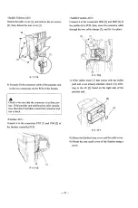
Page 46: ...the height of the finisherby 1 75 mm Refer to the index on the casterwhile turning the bolt and perform this for both front and rear casters Making Checks after Adjustment 1 Check to see once again th...

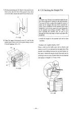
Page 47: ...Connect the finisher and the host machineusing an interface cable I Saddle Finisher AE2 1 Remove the punch lower front cover and the punch rear cover three screws and remove the stepped screw at the...

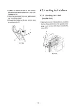
Page 48: ...ront cover and the punch rear cover three screws 10 Connect the finisher and the host machine using an interface cable I 4 3Attaching the Labels etc 4 3 1 Attaching the Label Puncher Unit 1 Openthe fr...

Reviews: