


VCO-6131E-4M2 l
User’s Manual
26
2.3 I/O Interface Descriptions
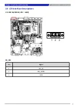
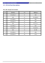
Pin
Definition
1
GND
2
OUT_R
3
GND
4
GND
5
OUT_L
Chapter 2: Switches and Connectors
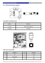
LINE_OUT1 :
Line-out Jack (Green) Connector Type: 5-
pin Phone Jack
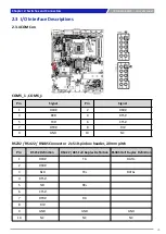
Pin
Definition
1
GND
2
MIC_R
3
GND
4
GND
5
MIC_L
MIC_IN1 :
Microphone Jack (Pink) Connector Type:
5-pin Phone Jack
LINE_OUT1
MIC_IN1
Summary of Contents for VCO-6131E-4M2
Page 1: ...VCO 6131E 4M2 Superior Fanless Embedded System...
Page 8: ...Chapter 1 Product Introductions...
Page 14: ...Chapter 2 Switches and Connectors...
Page 53: ...Chapter 3 System Setup...
Page 79: ...VCO 6131E 4M2 l User s Manual 79 7 Remove the SFF 8654 x8 cable Chapter 3 System Setup...
Page 87: ...VCO 6131E 4M2 l User s Manual 87 22 Close the chassis cover Chapter 3 System Setup...
Page 88: ...Chapter 4 BIOS Setup...
Page 91: ...VCO 6131E 4M2 l User s Manual 4 3 Advanced Setup 91 Chapter 4 BIOS Setup...
Page 117: ...VCO 6131E 4M2 l User s Manual PCI Express Configuration 117 Chapter 4 BIOS Setup...
Page 129: ...Copyright C T Solution Inc All Rights Reserved www candtsolution com...