


1.
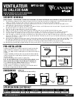
PREPARATION FOR MOUNTING (FIGURE 1)
Determine thickness of finished ceiling board (* measurement shown in
FIGURE 1). Place fan unit body against ceiling joist in desired location.
Ensure bottom of main body hangs down below joist to account for
finished ceiling board.
2.
MOUNTING FAN BODY (FIGURE 2)
Use long wood screws to loosely attach both sides of main body to joist
(right side shown). Ensure ventilation fan is level and that proper clearance
is given for finished ceiling board. When main body is level and in the
intended location, tighten screws on both right and left side of main body.
3.
USING QUICK CONNECT (FIGURE 3)
WARNING: Wiring must comply with all applicable electrical codes.
Turn power OFF before removing or installing connectors.
WARNING: COPPER to COPPER ONLY. Do not use on Aluminum wire.
CAUTION: The Quick Connect accessory part should be installed as
per instructions below.
NOTE: Connector is reusable on solid wires of the same wire gage or
smaller. Do not reuse connector on stranded wires.
a) Strip the wires so half of the bare wire is showing.
b)
Grip the wire firmly and push the stripped end of the wire into the open
port of connector). Use only one stripped end of the wire per port.
c)
Verify the stripped end of the wire is fully inserted to the back of the
connector.
NOTE: Important wire information. Maximum temperature rating 105°C (221°F).
600 volts maximum for building wire and 1000 volts maximum in signs and
lighting fixtures. Flammability rating of the wires must meet UL94-V2. The
acceptable wire range includes: Solid: 12-20 AWG, Stranded: 12-16 AWG (≤19
STRAND); 18AWG (7 STRAND), Tin bonded: 14-18 AWG (≤19 STRAND).
BEFORE YOU BEGIN
ITEM
PICTURE
QUANTITY
Fan Unit
1
Spring Clips
2
Grill
1
ITEM
PICTURE
QUANTITY
Quick Connect
3
Long Wood Screw
(4 x 30mm)
8
Screw
(4 x 6mm)
4
Bracket
4
HVAC PRODUC S
HVAC PRODUC S
HVAC PRODUC S
BPT12-13H
BATHROOM EXHAUST FANS
BPT12-13H-M-05_05_15
Page 2 of 3
WARNING: TURN OFF ELECTRICITY AT BREAKER BOX
BEFORE BEGINNING INSTALLATION
INSTALLATION INSTRUCTIONS
1.
Carefully unpack and remove the unit from the carton.
2.
Check to make sure you have all components listed in the tables
shown right and below.
3.
If any components are missing, please contact the manufacturer.
FIGURE 1
FIGURE 2
QUICK
CONN
E
C
T
HOUS
E
WIR
E
S
PRODUC
T
WIR
E
S
FIGURE 3


