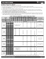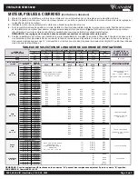
9200 SERIES BLOWERS
9200_9200_VIB_UserGuide_02_09_2023
Page 3 of 3
ELECTRICAL
1.
Complete the electrical connections, energize the unit momentarily and ensure proper wheel rotation
2.
Apply full power.
3.
With all ducts attached, the access doors in place and the air system in full operation, measure the motor current and ensure that it is
less than the rated full load motor amperage as indicated on the motor nameplate.
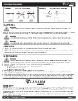
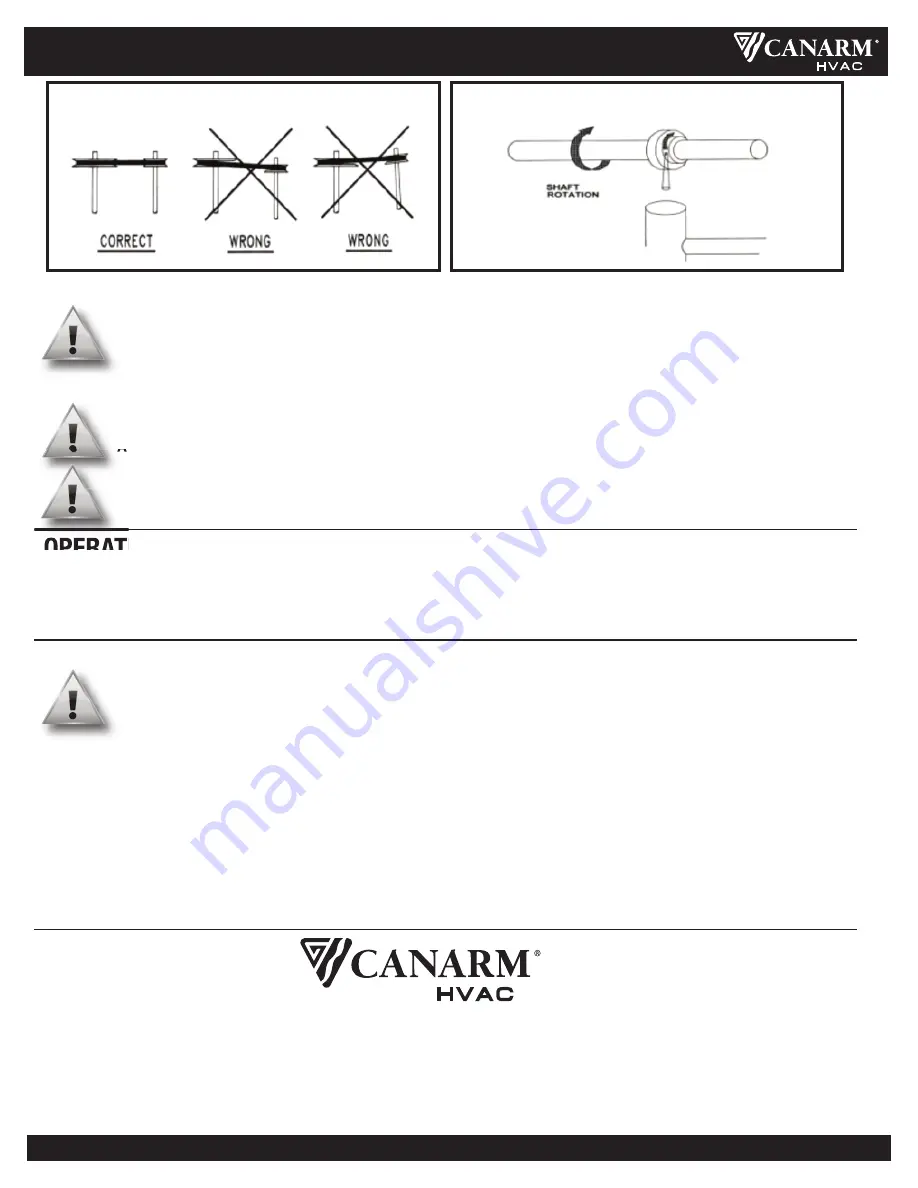
PULLEY ALIGNMENT
FIGURE 1
FIGURE 2
WARNING
ENSURE POWER SUPPLY IS DISCONNECTED & LOCKED OUT PRIOR TO MAKING ELECTRICAL CONNECTIONS.
WARNING
A GROUND WIRE MUST BE CONNECTED FROM THE MOTOR HOUSING TO A SUITABLE ELECTRICAL GROUND.
WARNING
ENSURE POWER SUPPLY IS DISCONNECTED & LOCKED OUT PRIOR TO MAKING ELECTRICAL CONNECTIONS.
BEARING REPLACEMENT
Before connecting the motor to the electrical supply, check the electrical characteristics and wiring instructions as indicated on the motor
nameplate or inside the conduit box cover to ensure proper voltage and phase. Complete electrical connections as indicated.
OPERATION
1.
Inspect and tighten all bearing collar and wheel set screws after the first 50 to 100 hours of operation and periodically thereafter.
2.
Follow motor manufacturer's instructions for motor lubrication. Remove any excess lubrication.
3.
Check the drives.
a.
Tighten set screws on pulleys, wheel and bearing locking collars.
b.
Check belt tension and alignment.
c.
Replace cracked or worn belts.
4.
Blower bearings are permanently lubricated and require no further lubrication.
5.
Inspect V-belts for wear and proper tension. If it is necessary to replace one belt on a multiple belt drive, replace all the belts with a
matched set. Do not use belt dressing.
6.
Clean the blower wheel periodically. Material build up on the blades can cause wheel imbalance which may result in wheel or bearing failure.
7.
To reinstall replacement ball bearings press the locking collar against the inner ring of the bearing and turn in the direction of the shaft
rotation until engaged. Insert a drift pin into the pin hole and tap lightly to set. Tighten set screw on locking collar firmly (see
Figure 2
).
MAINTENANCE
WARNING
A GROUND WIRE MUST BE CONNECTED FROM THE UNIT CHASSIS TO A SUITABLE ELECTRICAL GROUND.
WARRANTY
CANARM Ltd.
warrants every new product to be free of defects in material and workmanship, to the extent that, within a period of one
year from the date of purchase
CANARM Ltd.
shall either repair or replace at
CANARM’s
option, any unit or part thereof, returned freight
prepaid, and found to be defective. This warranty does not include any labour or transportation costs incidental to the removal and
reinstallation of the unit at the user’s premises.Components repaired or replaced are warranted through the remainder of the original
warranty period only.
This warranty applies to the original purchaser-user only; it is null and void in case of alteration, accident, abuse, neglect, and operation
not in accordance with instructions.


