13
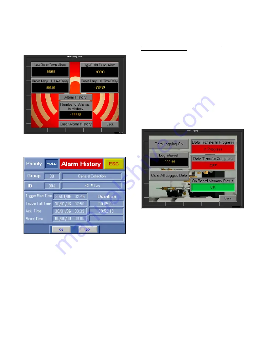
Temp. Alarm>, a new alarm will activate after < Outlet
Temp. LL Time Delay > seconds. Should the DHW outlet
temperature fall back within the range set between <Low
Outlet Temp. Alarm> and <High Outlet Temp. Alarm>
before the time set in the time delays is reached, the alarm
will not activate.
Down from DHW outlet temperature high and low limit
alarms, pressing <Alarm History> will take the user to a
screen that shows details about the history of alarms:
While the <Number of Alarms in History> is a display that
shows the number of alarms currently held in <Alarm
History>, pressing <Clear Alarm History> will clear all
alarms in history turning <Number of Alarms in History> to
zero. It should be noted that a Modbus Master can also
clear alarms from the history provided that they are no
longer active. Please refer to Modbus Mapping table in
section 5.1.
5.2.3.2
– <Data Logging>
To use the data logging feature of DynaFLO
’s controller a
computer, a software called DataXport and a USB cable are
needed.
DataXport allows the user to set automatic schedules for
data that has already been collected by DynaFLO
’s
controller to be transferred to a computer. Once data has
been transferred to the computer onto DataXport, CSV,
Text or Excel files can be generated.
DataXport can be downloaded for free from:
https://unitronicsplc.com/software-visilogic-for-
programmable-controllers/
Instructions on how to use DataXport are given in the next
section.
Once DataXport is set up and DynaFLO
’s controller is
connected to the computer using a USB cable, data logging
can begin. On DynaFLO
’s controller, the following
parameters are logged when <Data Logging ON/OFF> is
turned ON:
RTD1
Actuator Position
Setpoint
Total
Number
of
Alarms
Pending
for
Acknowledgement
Date and Time
<Log Interval> allows the user to select the time interval for
logging data. Once <Log Interval> is set and <Data Logging
ON/OFF> is switched ON data is then collected onto a table
that is built into the controller’s internal memory. This table
has a 1000 rows, therefore depending on what the <Log
Interval> is set at, the table fills up. For example if the <log
Interval> is set at 1 second, after a 1000 seconds (16.66
minutes) the table fills up. If <Log Interval> is set at 60
seconds, table fills up after 60,000 seconds (16.66 hours)
and so on. Data is accumulated onto the built in table in
FIFO (First In First Out) which means that once the 1000
rows in the data table are filled up, the controller starts from
the beginning of the table again overwriting the values
previously stored in row 1.
Pressing <Clear All Logged Data> clears the built in data
table instantly, regardless of whether it is yet transferred to
DataXport or is filled up.
<Data Transfer In Progress> is an indicator that turns <In
Progress> when DataXport is in the middle of copying data
from DynaFLO
’s built in data table in the controller. <Data
Transfer Complete> is another indicator that turns ON once


