


B-1
Appendix B. Installation Scenarios
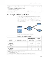
B.1 Example 1: PC-to-RF Network
In this example, the master radio is connected to a PC running
LoggerNet
(see
). Slave radios are connected to CR1000s in the field.
LoggerNet
may be used to view real-time values from the dataloggers, collect data, set
datalogger clocks, and send programs.
Remember, each datalogger must have a unique PakBus® address.
Master
RF451
Slave
Slave
Slave
PC Running
LoggerNet
/PC400
FIGURE B-1. Schematic of PC-to-RF451 Network
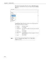
Using
DevConfig,
set up the master and slave RF451 radios according to
Deployment
tab of
DevConfig
should look similar to
TABLE B-1. RF451 Settings for Example 1
Master
Slave(s)
Hardware
RF451 connected to PC running
LoggerNet
RF451 connected to CR1000
CS I/O port
Keep all factory default settings except:
Active Interface
USB or RS-232 (to match how
LoggerNet
will be communicating with
the radio)
CS I/O SDC (with SDC Address set to
an unused SDC address on the
datalogger)
Radio Operation Mode
Multi-Point Master
Multi-Point Slave
Network ID
1726 (yours may be different)
1726 (yours may be different)
Frequency Key
1 (yours may be different)
1 (yours may be different)
Radio ID
4094 (to match
LoggerNet
PakBus
address)
2 (to match CR1000 PakBus address)*
* All slave Radios in the network will have these same settings except for the
Radio ID
. The
Radio ID
should
match the PakBus address of the datalogger it is connected to.
Summary of Contents for RF451
Page 2: ......
Page 6: ......
Page 10: ...Table of Contents iv ...
Page 34: ...RF451 Spread Spectrum Radio 24 ...
Page 36: ......
Page 46: ...Appendix B Installation Scenarios B 10 ...
Page 58: ...Appendix D Distance vs Antenna Gain Terrain and Other Factors D 10 ...
Page 60: ......
Page 61: ......