Campbell Company
Guardian Installation Manual
906-0056 Guardian Installation Manual Rev A.docx
© Dick Campbell Company 2020. All rights reserved
Page 8 of 11
3.2.3
400A Station Installation
1. Route the four conductor cable from the pedestrian signal head though the hole in the
station housing.
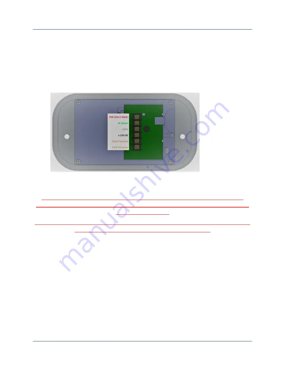
2. Connect the four conductor cable to the terminal block on the back of the station to the
positions shown in Figure 2.
3. If there are pedestrian field wires present at the station, connect them to the positions
shown in Figure 2.
4. Insert the pushbutton into the 400 style housing and secure using two 1/4-20 screws.
Figure 2
3.2.4
Signal Power Interface Installation
Do not set the SPI on the bottom of the Pedestrian Signal Head. Failure to attach the SPI
vertically on the back surface wall can expose the power supply to water damage and will void
the warranty of the SPI.
Warning! All SPI leads become hot when at least one of the wires is connected. Disconnect the
power to the Pedestrian Signal Head prior to SPI installation
1. Disconnect the power going to the Pedestrian Signal Head prior to installing the SPI.
2. Open the Pedestrian Signal Head Display and locate a ¼-20 tapped hole on the back
wall close to the 120VAC three position barrier strip as shown in Figure 2.


