
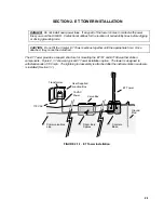


SECTION 3. ET INSTRUMENTATION INSTALLATION
3-8
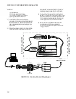
At the PC:
(1) Rad Modem
(1) 5 foot 4-wire Patch Cable
(1) 10 foot 14 AWG Ground Wire
(1) Surge Protector and Case
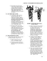
1) Connect the 20 foot patch cable to
connector #8 on the external back panel of
the ET Enclosure. Splice this cable to the
user supplied cable, using the direct bury
splice kits.
2) Mount the surge protector to a flat surface
within 10 inches of the PC's serial port.
Ground the center terminal to an earth (or
building) ground using the 14 AWG wire.
3) Connect the 5 foot patch cord to the Rad
Modem. Fasten the cable to the strain relief
tab with a cable tie. Connect the Rad to the
PC's serial port either directly (25 pin port)
or through a 9 to 25 pin serial converter.
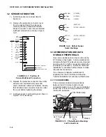
4) Route the user-supplied cable from the
remote splice to the surge protector.
Connect it and the 5 foot patch cord to the
surge protector.
- RCV (white)
- RCV (black)
+ RCV (green)
+ RCV (red)
+ XMT (red)
+ XMT (green)
- XMT (black)
- XMT (white)
- RCV
+ RCV
+ XMT
- XMT
BLACK
RED
GREEN
WHITE
2
1
3
4
- RCV (black)
+ RCV (red)
+ XMT (green)
- XMT (white)
2
1
3
4
SRM-5A
Surge
Protector
PC
User
Supplied
Cable
Splices
ET106 ENCLOSURE
ET106 ENCLOSURE
To # 8
External Connector
Earth Ground
CAMPBELL
SCIENTIFIC LTD
SC932 - S/N E1055
QC
FIGURE 3.3-5. Short-Haul Modem Wiring Diagram
Summary of Contents for ET101
Page 4: ...This is a blank page ...
Page 12: ......
Page 26: ......
Page 30: ......
Page 32: ......
Page 36: ......
Page 37: ...This is a blank page ...