


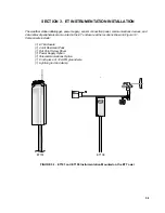


SECTION 2. ET TOWER INSTALLATION
2-3
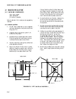
2.2 TOWER INSTALLATION
2.2.1 SUPPLIED COMPONENTS
(1) Upper Tower Section (Tapered)
(1) Lower Tower Section
(6) ½ inch Washers
(1) 12 foot 12 AWG Ground Cable
(1) Tower Cap
(1) 20' communications cable
(1) 20' power cable
Refer to Section 1 for components supplied by
installer.
2.2.2 INSTALLATION
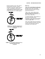
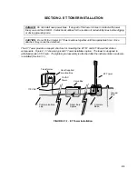
Attach the tower to the base as shown in Figure
2.2-1
1. Dig a hole close to the concrete base to
access the lower conduit opening. From
the hole, trench to the power and
communications sources. Remove the duct
tape from both ends of the conduit.
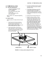
2. Remove the template. Attach the two
pieces of the tower. This is a permanent
connection and cannot be undone. Lay the
tower on the ground with the base next to
the concrete foundation.
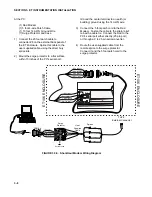
3. Thread communications and power cables
through the tower and conduit. Electrical
fish tape will help.
4. Cut and save a 9 inch piece of 12 AWG
ground wire from the 12 foot length
provided. Thread the remaining 11 foot
ground wire through the tower. Secure all
wiring so it does not slip back into the tower
or conduit.
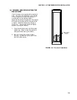
5. Place the tower cap over the tower end.
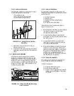
6. Raise the tower on a still day. Place a
washer on top of the two nuts on each
foundation bolt. Taking great care not to
damage cables between the tower and
conduit, raise the tower and lower it onto
the conduit and mounting bolts. Install a
washer and nut on each bolt and hand
tighten. Check plumb of the tower by
placing a level on the north and east sides
of the lower tower section. Adjust the
topmost of the two lower nuts (leveling nut)
on each bolt as necessary. When plumb is
established, lock the leveling nut in place by
tightening the lowest nut against it. Tighten
the three top nuts with the wrench.
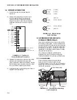
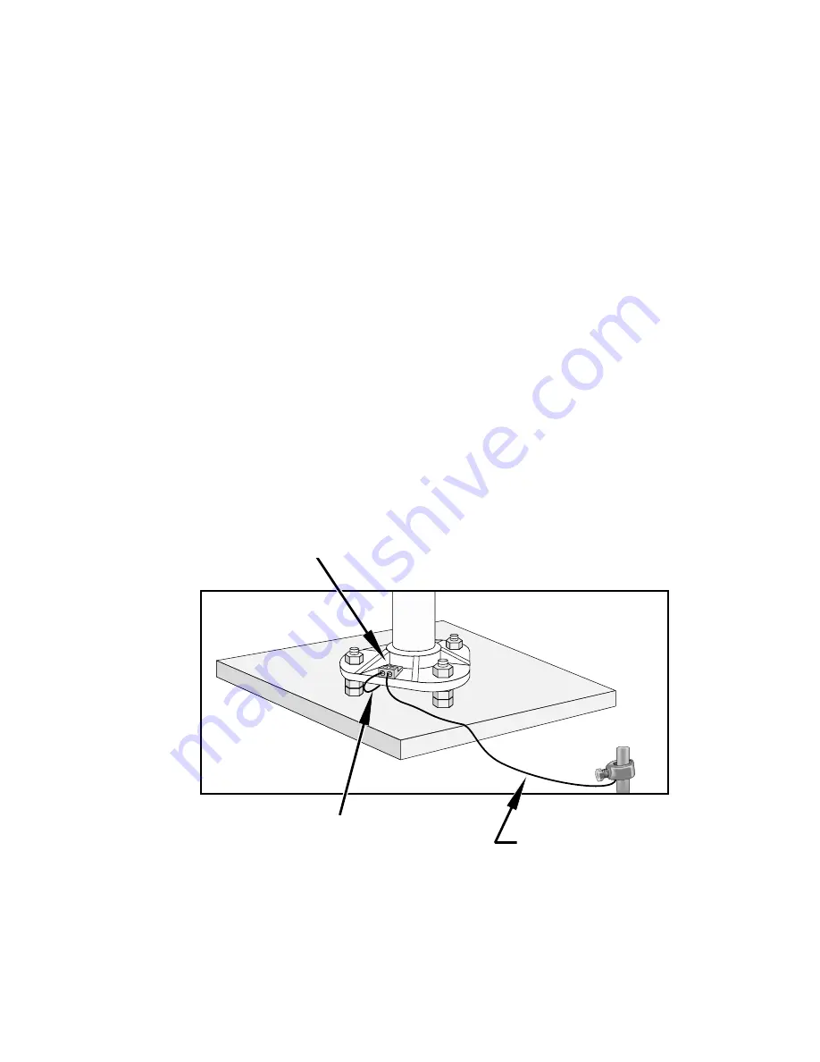
12AWG Wire
4AWG Cable
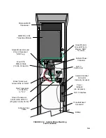
FIGURE 2.2-1. Raising and Grounding the ET Tower
Summary of Contents for ET101
Page 4: ...This is a blank page ...
Page 12: ......
Page 26: ......
Page 30: ......
Page 32: ......
Page 36: ......
Page 37: ...This is a blank page ...