Campbell CS475 Instruction Manual Download Page 44

Appendix C.  SDI-12 Commands/ Changing Settings 

C-10 

C.2.2  CR200(X) Series Datalogger Example 

1.


Connect a single sensor to the datalogger as follows: 


White to Control Port C1/SDI12 


Black, Clear to G 


Red to B 

2.


In the 

LoggerNet Connect 

screen navigate to the Datalogger menu and 

select Terminal Emulator. The “Terminal Emulator” window will open. In 

the Select Device menu, located in the lower left-hand side of the window, 

select the CR200Series station.  

3.


Click on the Open Terminal button.  

4.


Press the <enter> key until the datalogger responds with the “

CR2XX>

” 

prompt. At the “

CR2XX>

” prompt, make sure the All Caps Mode box is 

checked and enter the command 

SDI12 

<enter>. The response “SDI12>” 

indicates that the sensor is ready to accept SDI-12 commands. 
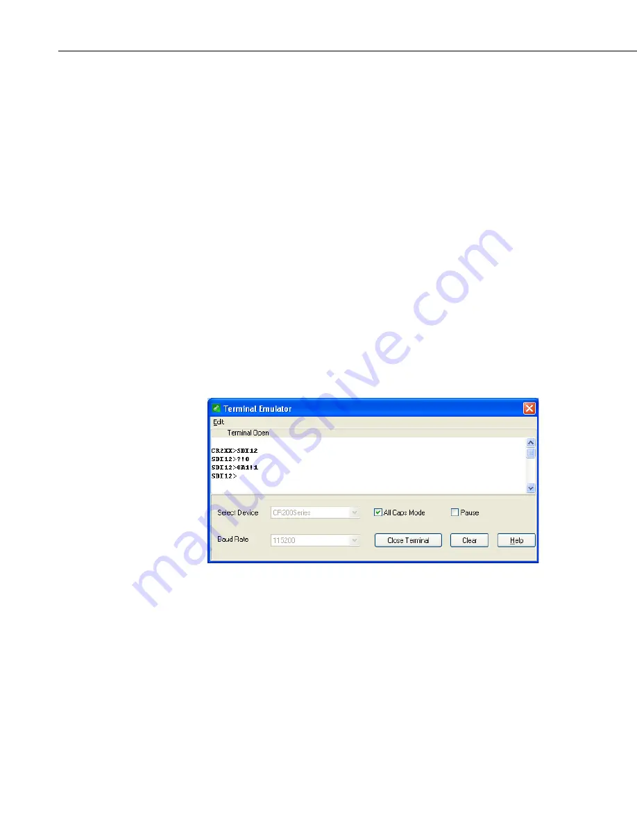
5.


To query the sensor for its current SDI-12 address, key in ?! <enter> and 

the sensor will respond with its SDI-12 address. If no characters are typed 

within 60 seconds, then the mode is exited. In that case, simply enter the 

command SDI12 again and press <enter>. 


FIGURE C-1.  SDI-12 transparent mode on CR200(X)-series datalogger 

using control port C1/SDI12 and changing SDI-12 address from 0 to 1 

6.


To change the SDI-12 address, key in 

aAb!<enter>

 where 

is the 

current address from the above step and 

is the new address. The sensor 

will change its address and the datalogger will respond with the new 

address. To exit SDI-12 transparent mode select the Close Terminal 

button.  

Summary of Contents for CS475

Page 1: ...INSTRUCTION MANUAL CS475 CS476 and CS477 Radar Water Level Sensors Revision 5 17 C o p y r i g h t 2 0 0 9 2 0 1 7 C a m p b e l l S c i e n t i f i c I n c...

Page 2: ......

Page 3: ...ucts to CSI CSI will return such Products by surface carrier prepaid within the continental United States of America To all other locations CSI will return such Products best way CIP port of entry per...

Page 4: ...ing address is CAMPBELL SCIENTIFIC INC RMA _____ 815 West 1800 North Logan Utah 84321 1784 For all returns the customer must fill out a Statement of Product Cleanliness and Decontamination form and co...

Page 5: ...beginning work Wear a hardhat and eye protection and take other appropriate safety precautions while working on or around tripods and towers Do not climb tripods or towers at any time and prohibit cl...

Page 6: ......

Page 7: ...n 11 7 2 Mount and Align the Sensor 11 7 3 Wiring to Datalogger 14 7 3 1 Built in Self Test BIST 14 7 4 Datalogger Programming 14 7 4 1 SDI12Recorder Instruction 15 8 Operation 15 8 1 Default Settings...

Page 8: ...s see TABLE 7 3 for label descriptions 13 9 1 Changing the electronics see TABLE 9 1 for label descriptions 20 C 1 SDI 12 transparent mode on CR200 X series datalogger using control port C1 SDI12 and...

Page 9: ...Table of Contents iii C 9 Acknowledge Active Command C 7 C 10 Send Identification Command C 8 C 11 Checking CRC Example C 9 CRBasic Example B 1 CR1000 Program Measuring the CS475 B 1...

Page 10: ...Table of Contents iv...

Page 11: ...cal safety and ANSI standards Depending on the model the emitting frequencies of these radar sensors are either in the C or K band range Their low transmitting power is well below the internationally...

Page 12: ...ed file a claim against the carrier and report the damage in detail 4 QuickStart Short Cut is an easy way to program your datalogger to measure the sensor and assign datalogger wiring terminals Short...

Page 13: ...ck Next 3 Under the Available Sensors and Devices list select the Sensors Water Level Flow folder Select CS475 CS476 CS477 Radar Water Level Sensor click to move the selection to the Selected device w...

Page 14: ...m in step 4 check the output of the sensor in the datalogger support software data display to make sure it is making reasonable measurements 5 Overview The CS475 CS476 and CS477 emit short microwave p...

Page 15: ...dar sensor consists of an integrated microwave transmitter and sensor together with a horn antenna see FIGURE 5 2 and TABLE 5 1 The horn antenna serves to focus the transmitted signal and to receive t...

Page 16: ...n of labels TABLE 5 1 Description of Components and Hardware Labels A CS475 B CS476 or CS477 1 Mounting Loop 2 PULS Housing Side Cap 3 PULS Housing Cap 4 PULS Unit Secondary 1 2 NPT Cable Port Primary...

Page 17: ...tion Rugged enough for harsh environments NEMA rated 4X Individual FCC license not required Compatible with Campbell Scientific dataloggers CR200 X series CR300 series CR6 series CR800 series CR1000 C...

Page 18: ...th 12 V Power Supply Sleeps 4 7 mA Measurement 14 mA 6 2 Environmental Operating Temperature Range 40 to 80 C Storage Ranges Temperature 40 to 80 C Relative Humidity 20 to 80 RH Temperature Sensitivit...

Page 19: ...CS475 CS476 and CS477 Radar Water Level Sensor 9 FIGURE 6 2 CS475 dimensions 86 mm 3 4 in 129 mm 5 1 in 122 mm 4 8 in 75 mm 3 in 86 mm 3 4 in 15 mm 0 6 in 115 mm 4 5 in...

Page 20: ...CS475 CS476 and CS477 Radar Water Level Sensor 10 FIGURE 6 3 CS476 CS477 dimensions 585 mm 23 in 430 mm 16 9 in 86 mm 3 4 in 86 mm 3 4 in 95 mm 3 7 in...

Page 21: ...tructural surfaces such as beams brackets and sidewall joints because these surfaces reflect a strong signal If these structures cannot be avoided use the False Echo Learn command to map out the inter...

Page 22: ...le Distance in Meters Diameter of Footprint in Meters 1 0 14 5 0 70 10 1 41 15 2 11 20 2 81 30 4 216 70 CS477 only 9 84 3 Securely mount the sensor 4 Use a user supplied bubble level or the 25619 bubb...

Page 23: ...ription 1 CS475 Polarization marks are designated by the mounting loop screws 2 CS476 CS477 Polarization mark is machine tooled After mounting you can rotate the housing up to 350 to simplify access t...

Page 24: ...ns 7 3 1 Built in Self Test BIST After connecting the sensor to the datalogger s power terminals the sensor performs a BIST built in self test for approximately 80 seconds factory default During this...

Page 25: ...irst index for stage measurement m or ft the second for distance m or ft and the third for an error code see Section 9 Diagnostics Repair and Maintenance p 16 The stage measurement calculation is base...

Page 26: ...to be returned when one or more subsequent aD commands are issued When using the aM command the datalogger waits for the time specified by the sensor sends the aD command pauses its operation and wait...

Page 27: ...ower mode is what you want 10 Use the False Echo Learn command aXSFEL nnn nnn if you encounter a problem that could be caused by noise 9 2 Cyclic Redundancy Check The cyclic redundancy check CRC is us...

Page 28: ...tarts 9 3 1 No Measured Value Available Error E013 If you are unable to find a measured value check the following Sensor in boot phase Update the Start False Echo Learn aXSFEL See Appendix C 1 3 Start...

Page 29: ...n removing the electronics because a seal is between the electronics and the lower portion of the housing 5 Replace the electronics with a new module Make sure the two 2 screws holding the electronics...

Page 30: ...see TABLE 9 1 for label descriptions TABLE 9 1 Description of Changing the Electronics Labels Description 1 Red Wire 2 Housing Top View 3 Screws to Secure Electronics to Housing 4 Electronics 5 Housi...

Page 31: ...Short Cut Make note of the file name used when saving the Short Cut program 2 Open CRBasic Editor 3 Click File Open Assuming the default paths were used when Short Cut was installed navigate to C Cam...

Page 32: ......

Page 33: ...r 60 minute maximum and minimums DataTable Hourly True 1 DataInterval 0 60 Min 10 Maximum 1 Distance FP2 0 0 Minimum 1 Distance FP2 0 0 Average 1 Distance FP2 False StdDev 1 Distance FP2 False Maximum...

Page 34: ......

Page 35: ...hen multiple sensors are connected to the same port Valid addresses are 1 to 9 A to Z or a to z Command body e g M1 an upper case letter the command followed by alphanumeric qualifiers Command termina...

Page 36: ...th 2 medium or 3 rough Set Water Stage1 aXSS n nnn n floating point number that is the initial stage or level of the water surface above the reference Where n is the new water stage Get Unit1 aXGU 0 m...

Page 37: ...initial water depth followed by the aD0 Send Data command TABLE C 4 shows an example of the command and response for entering this setting TABLE C 4 Example for Setting Water Stage Initial Command Res...

Page 38: ...ess This is the send data command 0 2 500 cr lf Where from left to right 0 sensor s address 2 500 the water surface distance C 1 4 Set Units The distance measurement can be reported in feet default or...

Page 39: ...ooth typical peak to trough of wave 4 2 medium typical peak to trough of wave 8 3 rough typical peak to trough of wave 8 The factory default water conditions are set to 1 which is smooth The water con...

Page 40: ...til a new set power command is received 2 AUTO sensor is powered by an incoming request from the SDI 12 bus and sends back a response including the information on power up time 0 OFF this mode is typi...

Page 41: ...e new power mode setting 2 auto Initial Command Response aXGPOM Where zero is the sensor address This is the get power mode command 00011 cr If Where from left to right 0 sensor s address 001 the amou...

Page 42: ...ntification Command Initial Command Response aI a13VEGAbbbbPS6233212345678 cr If Where from left to right a sensor address 13 SDI 12 compatibility number VEGA Manufacturer s Name PS62 Manufacturer s M...

Page 43: ...n manually interrogate and enter settings in probes using transparent mode Transparent mode is useful in troubleshooting SDI 12 systems because it allows direct communication with probes Datalogger se...

Page 44: ...ps Mode box is checked and enter the command SDI12 enter The response SDI12 indicates that the sensor is ready to accept SDI 12 commands 5 To query the sensor for its current SDI 12 address key in ent...

Page 45: ...here the sensor s white lead is connected and enter The response Entering SDI12 Terminal indicates that the sensor is ready to accept SDI 12 commands 5 To query the sensor for its current SDI 12 addre...

Page 46: ...Appendix C SDI 12 Commands Changing Settings C 12...

Page 47: ...t approved by Campbell Scientific will cause the expiration of the operating license issued by the FCC IC The radar sensor is in conformity with Part 15 of the FCC directives and fulfills the RSS 210...

Page 48: ......

Page 49: ......

Page 50: ...ua Apinag s nbr 2018 Perdizes CEP 01258 00 S o Paulo SP BRASIL www campbellsci com br vendas campbellsci com br Campbell Scientific Canada Corp 14532 131 Avenue NW Edmonton AB T5L 4X4 CANADA www campb...

Reviews: