background image

CS120A and CS125 Visibility and Present Weather Sensors 

40 

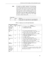
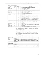
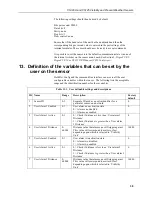
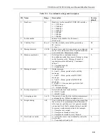
Table 13-1.  User definable settings and descriptions 

ID  Name 

Range 

Description 

Factory 

default 

18  Hood heater override

(1)


0-1 

0 = Allow the sensor to automatically control the 

hood heaters 

1 = Turn the hood heaters off 

19  Dirty window 

compensation 

0-1 

0 = No compensation applied 

1 = Compensation for dirt on lenses applied. 

The sensor will compensate for up to 10% signal 

loss due to dirt per lens. 

 0 

20  Use CRC-16 

0-1 

0 = Disable command line CRC-16 checking

(2)


1 = Enable command line CRC-16 checking 

Note: this does not affect communications via 

DevConfig or terminal emulator. 

21  Sensor power down 

voltage 

7-30 

PSU Input voltage level below which the sensor 

will enter low power mode. This is usually used to 

protect batteries. 

7.0 

22  Relative humidity

(3)


threshold 

1-99 

Threshold at which the sensor will define 

obscuration as liquid or dry if a CS215 is fitted. 

80% 

(1) Hood heater override needs to be set to ‘1’ (off) when either no hood heaters are installed or the 

hood heaters have no power connected to them.  This will save power as the relay is not enabled at 

low temperatures in this mode.  
(2) If disabled the sensor does not check the validity of received data against the checksum sent. It 

is, however, recommended that checksum checking is enabled to remove any chance of the sensor 

being configured incorrectly by accident. 
(3) CS125 only. 

14.  Command line mode 

The command line interface is broken down into three major commands.  

These are GET, SET and POLL. The GET command is used to request all 

current user settable values from the sensor. The SET commands sets user 

settable values and the POLL command is used to request the current visibility 

and/or alarm conditions from the sensor. 
The sensor can be configured to expect any commands sent to it to include a 

valid checksum. For simple commands, e.g. GET and POLL, fixed value 

checksums can be used (see the downloadable example programs at 

www.campbellsci.com/downloads/cs125-example-programs

 or 

www.campbellsci.com/downloads/cs120a-example-programs

). For more 

complex SET commands the checksum needs to be calculated (see Appendix 

B

Example C code of the CRC-16 checksum


(p. B-1)

). The use of the checksum 

is disabled by default. It is recommended that the checksum functionality is 

enabled where possible, especially when long cable runs are used, or in 

electronically noisy environments. 

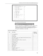
14.1  The SET Command 

The set command is used to configure the sensor via the command line.  The 

SET command is a single space delimited string that can be sent from any data 

logger or PC equipped with serial communications.  The SET command and 

the ‘Device Configuration Utility’ software access identical settings within the 

sensor, please refer to the ‘Device Configuration Utility’ section of this 

document for a more detailed breakdown of the setting available here. This 

command is used to change the default power up state of the sensor. See 

Summary of Contents for CS120A

Page 1: ...CS120A and CS125 Visibility and Present Weather Sensors Revision 10 2020 Copyright 2013 2020 Campbell Scientific Inc...

Page 2: ...ommunications specification 8 4 1 Communications electrical specifications 8 4 2 Supported data rates and formats 8 5 Environmental specifications 9 6 Mechanical specifications 9 6 1 Dimensions 9 6 2...

Page 3: ...nition of the variables that can be set by the user on the sensor 38 14 Command line mode 40 14 1 The SET Command 40 14 1 1 Example of a SET Command 41 14 2 The SETNC Command 42 14 2 1 Example of a SE...

Page 4: ...1 Airflow 11 7 2 Grounding boss 12 7 3 Mounting arrangement 13 7 4 Mounting to a flat surface 14 7 5 Use of band clamps 14 7 6 Optical sensor mast 15 7 7 Mounting footprint 16 8 1 Connections 18 8 2 C...

Page 5: ...orward scatter system for visibility measurement utilising a 42 scatter angle The CS125 uses high speed sampling to reduce missed events and improves response to other suddenly changing conditions The...

Page 6: ...ght useful information in the installation use and maintenance of this product These should be followed carefully in order to gain the maximum benefit from the use of this product 1 2 Sensor unit safe...

Page 7: ...nal to the extinction of the emitted beam caused by scattering The scattering signal averaged over one second is used to calculate an extinction coefficient or EXCO Sixty one second averages are then...

Page 8: ...ure and relative humidity probe is connected then a wet bulb temperature can be calculated This provides useful additional information identifying particles more accurately especially between liquid a...

Page 9: ...8N1 38400 baud a sensor ID 0 and set to transmit default messages full format visibility only for the CS120A SYNOP present weather full format for the CS125 at 1 minute intervals see Section 11 Messa...

Page 10: ...ion range 0 999 9 mm Accumulation accuracy 15 Accumulation resolution 0 1 mm Reported intensity range up to 0 999 99 mm hr Intensity accuracy 15 Intensity resolution 0 01 mm hr The maximum intensity r...

Page 11: ...e not being used ensure Hood heater override details in Section 13 Definition of the variables that can be set by the user on the sensor p 38 is set to off 4 It is recommended that the hood heaters ar...

Page 12: ...V 1 The RS 232 communications interface will automatically turn itself off when not transmitting 2 The ground of the sensor and the ground of any RS 485 equipment cannot be further apart than this vol...

Page 13: ...Sensor humidity ranges Operating humidity range 0 100 Sensor heater thresholds Dew heater Turn On 35 C Dew heater Turn Off 40 C Hood heater Turn On 15 C Hood heater Turn Off 25 C 1 Extended temperatu...

Page 14: ...ern hemisphere or south in the southern hemisphere but this is not critical if the field of view does not include a bright and scattering surface To give non microclimatic measurements the sensor shou...

Page 15: ...e sources of light and or reflections that will create false readings and erratic results If carrying out simple checks blocking a lens or the sample volume will simulate an INCREASE in visibility not...

Page 16: ...nted away from the sensor head to avoid wind flow disturbance or rain drops bouncing back up into the sensor s sensing volume Take care not to overtighten the nuts on the bolts as it may be possible t...

Page 17: ...sistance to water ingress Figure 7 3 Mounting arrangement If you need to mount the sensor to a flat surface remove the plastic formers from the mounting brackets and use the holes as shown in Figure 7...

Page 18: ...CS125 Visibility and Present Weather Sensors 14 Figure 7 4 Mounting to a flat surface Slots are provided to allow band clamps to be used with larger diameter masts see Figure 7 5 Figure 7 5 Use of ba...

Page 19: ...mpbell Scientific Mount A Campbell Scientific optical sensor mount is available This will put the sample volume at about 1 5 m in compliance with the WMO Guide to Meteorological Instruments and Method...

Page 20: ...and concrete foundation Drill four 12 mm diameter holes using the mount base as a template or following Figure 7 7 to a depth of 77 mm Figure 7 7 Mounting footprint Clean the holes of all debris Plac...

Page 21: ...ted with a 5 m cable Glands 3 and 4 are spare If user alarms are connected they usually use gland 3 and if a CS215 is fitted this usually uses gland 4 If you need to run cables through the cable gland...

Page 22: ...h This is for the hood heater power supply If the hood heater supply is DC it should be the positive connection To avoid damage to noise filters on the hood heater inputs if the heater voltage is DC t...

Page 23: ...only Pin number Description Pin 1 12V Pin 2 SDI 12 Pin 3 0V To use these connections it is necessary to either use the cable gland taking the hood heater power or if the hood heater is also required...

Page 24: ...n cable are available from Campbell Scientific that plug directly into connector B in place of the normal connector and cable One has a RS 232 or RS 485 output according to how the CS120A CS125 is con...

Page 25: ...ill be much improved by a CS215 and its use is highly recommended in regions where temperatures close to 0 C are common if information on precipitation type is important It also allows RH information...

Page 26: ...e ground The screen should be below the height of the CS125 electronics box Figure 9 1 Connection for the optional HygroVUE 5 HygroVUE 10 and CS215 T RH sensors CS215 WIRING COLOUR FUNCTION PIN Red 12...

Page 27: ...in functions at power up their functions are detailed in Table 10 1 The switches are only read during the power up sequence of the sensor This means that if the switches are pressed whilst the sensor...

Page 28: ...ues This reset will affect all communication settings This will take immediate effect upon power up NOTE To use this the power supply must be stable Do not leave this switch set permanently If the lid...

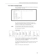
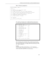
Page 29: ...ITT ETX Carriage return Line feed 0x02 0 M or F XXXX 0x03 0x0D 0x0A 0 0 0 19837 M FC92 Example message visibility units metres In the following example messages where shown message intervals are 12 se...

Page 30: ...th Visibility Units Metres 11 2 Messages with SYNOP Present Weather Codes CS125 only SYNOP Present Weather Basic Format STX Message ID Sensor ID System status Visibility distance Visibility units SYNO...

Page 31: ...24 1 99 CAFA Example message 11 3 Messages with METAR Present Weather Codes CS125 only METAR Present Weather Basic Format STX Message ID Sensor ID System status Visibility distance Visibility units ME...

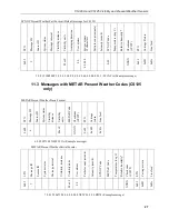
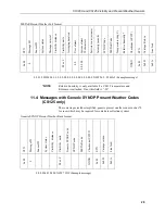
Page 32: ...0 0 0 0 0 0 0 0 0 0 0 00 0 NSW 24 2 99 40A2 Example message Relative humidity is only available if a CS215 temperature and RH sensor is attached If not this field is 99 11 4 Messages with Generic SYN...

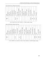
Page 33: ...M or F 0 0 XXXX 0x03 0x0D 0x0A 10 0 0 12 20909 M 0 0 0 0 00 0 0 NSW 24 2 99 AB02 Example message Generic SYNOP Present Weather Full format STX Message ID Sensor ID System status Message interval Visib...

Page 34: ...present weather format 12 Custom output CS125 only Sensor ID break down ID Definition 0 9 Unit number defined by the user to aid identification of data Zero by default Useful for RS 485 networks Oper...

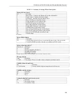
Page 35: ...tter hoods main LED output power level 0 2 0 3 3 0 Everything is within normal parameters 1 Light output level too low 2 Light output level too high Emitter lens dirty 0 3 0 3 1 2 0 OK The reported at...

Page 36: ...reading user variables from flash occurred Flash write error 0 1 0 3 0 No errors 1 One or more errors writing user variables to flash occurred Particle limit CS125 only 0 1 0 1 0 No errors 1 More par...

Page 37: ...External temperature in degrees Celsius Relative humidity Range Definition 0 100 External relative humidity in RH 99 indicates either a fault or no CS215 T RH sensor is connected CS125 only see Appen...

Page 38: ...tance Visibility units Up to 16 custom fields Checksum EOT 0x02 12 M or F X X X XXXX 0x04 There are two ways to configure the custom message The first is through the user menu system The second is thr...

Page 39: ...age field you wish to use and type return The screen will update with a 1 next to the chosen field Repeat for each field you want then exit the menu The changes take effect after selecting Exit and Sa...

Page 40: ...em alarms 12 4 Dirty windows values as percentages emitter followed by detector 2 5 Sensor serial number 1 6 Particle count 1 particles in the previous minute 1 7 Intensity 1 mm hr 1 8 Accumulation 1...

Page 41: ...g system The Device Configurator can also be used as a terminal emulator to use the built in menu system of the sensor and to access its calibration menu The second method is by using the command line...

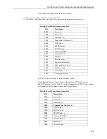
Page 42: ...these variables Table 13 1 User definable settings and descriptions ID Name Range Description Factory default 1 Sensor ID 0 9 Separate ID used as an extra identifier for a particular sensor on a netw...

Page 43: ...ontinuous Interval 0 Continuous mode 1 Polled mode 0 13 Message Format 0 12 Output message 0 1 and 2 Basic partial or full visibility messages 3 4 and 5 Basic partial or full SYNOP messages 6 7 and 8...

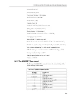
Page 44: ...ly by accident 3 CS125 only 14 Command line mode The command line interface is broken down into three major commands These are GET SET and POLL The GET command is used to request all current user sett...

Page 45: ...User Alarm 2 Active User Alarm 2 Distance Serial Baud Rate Sensor serial number read only Visibility Units Message interval Polling or Continuous modes Message Format RS 232 or RS 485 serial communica...

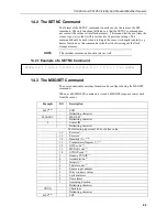
Page 46: ...e of a SETNC Command 14 3 The MSGSET Command The user customisable message format can be configured using the MSGSET command When a valid MSGSET command is issued a MSGGET response comes back from the...

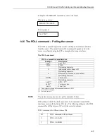
Page 47: ...0 Accumulation 0040 Intensity 0020 Particle count 0010 Sensor serial number 0008 Dirty windows values 0004 System alarms 0002 User alarms 0001 Averaging duration The HEX value is the sum of all the re...

Page 48: ...sor including message format data and user alarm settings amongst others This command does not retrieve visibility or environmental information from the sensor To retrieve visibility data refer to the...

Page 49: ...ontinuous modes Message Format RS 232 or RS 485 serial communications enabled Averaging Period Sample timing Dew heater override Hood heater override Dirty window compensation CRC 16 checking on recei...

Page 50: ...the dew heaters Hood heater override 0 sensor will automatically control the hood heaters Dirty window compensation 0 dirty window compensation off CRC 16 checking on received commands 1 CRC 16 checki...

Page 51: ...acter 0 Address based on Sensor ID Delimiting character 0 Reserved for future use zero default Delimiting character XXXX Checksum 3 Delimiting character 0x03 1 ETX C 2 0x0D 1 Carriage return 0x0A Line...

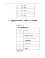
Page 52: ...mmand resets the accumulation to zero See Section 11 6 Custom message format p 34 The ACCRES command ACCRES command transmitted data Example Description 0x02 1 STX B 2 ACCRES ACCRES Delimiting charact...

Page 53: ...nu The displayed options are accessed simply by typing the corresponding number then pressing return No changes will take effect until you save and exit The exception to this is the calibration menu b...

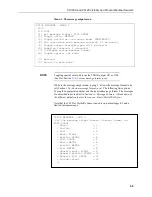
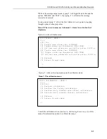
Page 54: ...34 While in the message output menu typing 1 allows the message format to be set Section 11 6 Custom message format p 34 The following lists options Typing the appropriate number sets the required me...

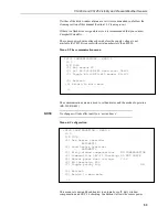
Page 55: ...menu Menu 3 The calibration menu Consult the calibration section Section 16 Calibrating the sensor p 54 of this manual for information on how to calibrate the sensor CS125 ALARM MENU 2 ID 0 S N 1009 1...

Page 56: ...coefficients from the latest calibration Menu 4 The system information menu NOTE CS125 INFORMATION MENU 4 ID 0 S N 1003 OS version 007646v1 Alarm Value Last visibility reading 3258M Overall system st...

Page 57: ...e mode of operation RS 232 RS 485 No change will take effect until you exit and save Menu 6 Configuration This menu sets dew and hood heaters to automatic or off dirty window compensation and CRC 16 c...

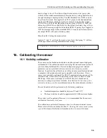
Page 58: ...n must be run using the onboard menu system If you have Campbell Scientific s Device Configuration program a terminal emulation screen is provided in the sensor screens to let you access this function...

Page 59: ...effect on the sensor At this stage it is advisable to clean the lenses Refer to Section 18 Cleaning p 60 for more information A simple visual check may be enough to confirm the lenses are clean Once...

Page 60: ...should appear indicating that the test is progressing as normal Remove the bungs once the sensor instructs you to Place the sensor calibrator into the volume by fastening it to the central mounting po...

Page 61: ...y All calibration constants including both the user and the factory setting can be viewed from menu item 4 from the main menu once the test is completed 16 2 Dirty window zero calibration Option 3 in...

Page 62: ...00 DO 4531 DD 1010 DO 4373 DD 1020 DO 4206 DD 1030 DO 3886 DD 1110 DO 2675 DD 1120 DO 2682 DD 1130 DO 2530 DD 1140 DO 2392 EO 3230 ES 371 DO 2251 DS 234 DD 1140 Press any key to exit Not return Press...

Page 63: ...refer to the help built into the DevConfig software for full instructions on how to update the sensor operating system The following figures show the procedure using DevConfig To use DevConfig to carr...

Page 64: ...exposure of the instrument to such contaminants This will vary depending on the site location The sensor is capable of self diagnosing dirty lenses and will indicate in its output when the lenses are...

Page 65: ...le anti seize grease often copper loaded to protect the threads from corrosion This should be reapplied when resealing the enclosure at regular intervals normally after replacing the desiccant This is...

Page 66: ...and Bentonite clay can be achieved at temperatures of 104 C 4 Desiccant bags should be allowed to remain in the oven at the assigned temperature for 24 hours At the end of this period the bags should...

Page 67: ...connects to the CS125 in the same manner as the WXT531 Either WXT sensor can be mounted on the same mast as the CS125 but care should be taken to ensure that it is placed to avoid the sampling zone fo...

Page 68: ...Addendum Hail monitoring CS125 only 64 Figure 1 Electrical connections between the WXT531 shown or WXT535 Hail Sensor and host CS125...

Page 69: ...A 1 Appendix A CS120A CS125 block diagram...

Page 70: ...tyle using a fast non table based algorithm Pass in the data to convert into a CRC 16 in the form of a NULL terminated character array a string Returns the CRC 16 in the form of an unsigned 16 bit int...

Page 71: ...er during the past hour 34 Fog depositing rime 35 PRECIPITATION 40 Precipitation slight or moderate 41 Precipitation heavy 42 Solid precipitation slight or moderate 45 Freezing precipitation slight or...

Page 72: ...S125 The following METAR codes from WMO table 4678 can be output by the sensor UP Unidentified precipitation HZ Haze BR Mist FG Fog DZ Drizzle RA Rain SG Snow grains SN Snow PL Ice pellets SMGR Hail N...

Page 73: ...Appendix C Present Weather Codes C 3 Z freezing may be added as a descriptor in front of L and R Intensity qualifiers for light for heavy may be added after the NWS code...

Page 74: ...ther manufacturer s products that are resold by Campbell Scientific are warranted only to the limits extended by the original manufacturer Refer to www campbellsci com terms warranty for more informat...

Page 75: ...ion or Repair Reference number contact your CAMPBELL SCIENTIFIC regional office Please write the issued number clearly on the outside of the shipping container and ship as directed For all returns the...

Page 76: ...and prohibit climbing by other persons Take reasonable precautions to secure tripod and tower sites from trespassers Use only manufacturer recommended parts materials and tools Utility and Electrical...

Page 77: ...nfo campbellsci fr www campbellsci fr Germany Location Phone Email Website Bremen Germany 49 0 421 460974 0 info campbellsci de www campbellsci de India Location Phone Email Website New Delhi DL India...

Reviews: