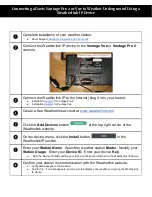
8. Click the Live Data tab to view real-time measurements.
The Quality Metric Sample value should be greater than
5.
WARNING:
Remove the USB cable before closing the door.
4. Wire functions and connections
Connect the wires in the order shown in the following table.
Table 4-1: Wire color, function, and data logger
connection
Wire color
Wire function
Data logger connection
White
SDI-12 signal
C, SDI-12, or U configured
for SDI-12
1
Red
Power
12V,
Black
Power ground
G
Blue
RS-232 TX
not connected
Yellow
RS-232 RX
not connected
1
U and C terminals are automatically configured by the
measurement instruction.
5. Mounting
CAUTION:
To prevent condensation, install the sensor in an
environmentally protected enclosure, complete with
desiccant. Change desiccant at regular intervals.
The BaroVUE 10 is typically mounted in a Campbell Scientific
enclosure next to the data logger. Secure the BaroVUE 10 to an
enclosure backplate by inserting screws through the mounting
holes in the BaroVUE 10 and into the grommets.
FIGURE 5-1. BaroVUE 10 mounted in a Campbell
Scientific enclosure

