


Section 2. Assembly of Components and Erection of Tower
2-13
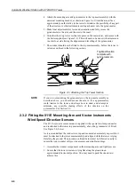
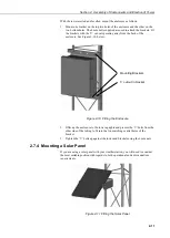
1. Cable glands will not seal directly onto most cables, especially
when more than one cable enters through a single gland. Please
refer to the Maintenance section for details.
2. The small cable gland on ENC series enclosures is for venting
purposes but may be used for additional cables
if venting is not
needed.
Please refer to the enclosure manual for further details.
5. Apply rustproofing compound as described in the Maintenance section.
2.9 Grounding and Lightning Protection
Two different grounding kits can be supplied with the UT towers. Roof mount
towers are supplied with basic clamps to allow the enclosure and tower to be
bonded together. A separate clamp is provided for connection of the tower to the
building earth system – the cabling and wiring of which should be done by an
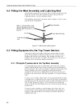
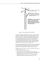
authorised electrician. A lightning spike is provided which should be fitted on the
top of the tower.
The grounding system for ground mounted towers consists of a lightning spike,
two copper-covered steel grounding spikes, grounding wire, clamps and
connectors. Install the grounding system as follows:
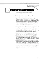
1. Screw the black Allen screw into the straight brass connector and then screw
the connector onto the blunt end of one of the copper-coated grounding
spikes. Drive the spike into the ground using the Allen screw as a driving
head. Position the spike as close as possible to the base of the tower.
2. Remove the Allen screw and screw the second spike into the straight
connector. Drive the second spike into the ground leaving about 100 mm
exposed above ground. This will drive the first spike to a depth of about 2.3 m
into the ground and should provide a good ground for lightning protection
purposes.
If the ground type does not permit you to drive the spikes in to a
total length of 2.3 metres then drive in the two rods individually,
spaced at least 2 metres apart, and join them together using a
length of the heavy gauge grounding wire, using additional clamps
(available from Campbell Scientific).
3. The lightning rod should already have been installed on the top of the tower as
shown in Section 2.2.
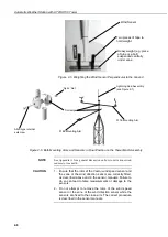
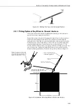
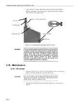
4. Connect the thicker grounding cable to the tower using the clamp provided
(the same type used to clamp the lightning spike to the top of the tower mast).
See Figure 2-12, below.
5. Connect the thinner grounding wire to the ground point on the underside of
the enclosure and tie it to the tower to reach the ground, also as shown in
Figure 2-12.
6. Connect
both
grounding cables to the exposed ground spike using the brass
grounding-bond clamp provided. If you had to install the spikes separately,
because of ground conditions, take the cable to the nearest spike. Try to keep
the length of wires used to a minimum, without coiling the wires. See
Figure 2-12.
NOTE
NOTE