background image

Model WF2034

Welding Guidelines 

(Continued)

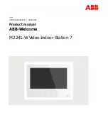
Figure 10 - Multiple Weld Passes

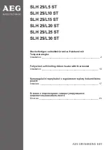
PUSH VS PULL TECHNIQUE

The type and thickness of the work piece
dictates which way to point the gun
nozzle. For thin materials (18 gauge and
up), the nozzle should point out in front
of the weld puddle and 

push 

the puddle

across the workpiece. For thicker steel,
the nozzle should point into the puddle
to increase weld penetration. This is
called backhand or 

pull 

technique (See

Figure 11).

PUSH

PULL

Figure 11

Normal Heat, Wire Speed, Travel

Speed

Heat Too Low

Heat Too High

Wire Speed Too Fast

Wire Speed Too Slow

Travel Speed Too Slow

Travel Speed Too Fast

Base Metal

Figure 12 - Weld Appearance

7

Supply Cable Replacement

1. Unplug welder.

2. Remove the right side panel.

3. Disconnect the black and white

power cord wires connected to the
ON/OFF switch.

4. Disconnect the green power cord

wire connected to the frame.

5. Loosen the cord strain relief screw

and pull cord through front panel.

6. Install new cord in reverse order.

www.chpower.com

Summary of Contents for WF2034

Page 1: ...ent requires a dedicated 115 volt circuit Refer to the following chart for the correct circuit breaker or fuse rating Do not run other appliances lights or tools on this circuit while operating this e...

Page 2: ...this equipment at current settings or duty cycles higher than those specified on the equipment labels Never use an electric arc welder to thaw frozen pipes Flying sparks and hot metal can cause injur...

Page 3: ...cautions a Remove the coating from the base metal b Make sure that the welding area is well ventilated c Use an air supplied respirator Extremely toxic fumes are created when these metals are heated T...

Page 4: ...e to 8 Activate the gun switch until the wire feeds out past the torch end See Figure 5 Turn welder off 9 Carefully slip the contact tip over the wire and screw it into the torch diffuser See Figure 6...

Page 5: ...nths 1 Replace any unreadable safety labels on the welder 2 Use compressed air to blow all dust and lint from the ventilation openings 3 Clean the wire groove on the drive roll Remove wire from the fe...

Page 6: ...speed is too fast the bead is narrow and bead ripples are pointed as shown When the speed is too slow the weld metal piles up and the bead is high and wide SLAG REMOVAL Wear ANSI approved safety glas...

Page 7: ...This is called backhand or pull technique See Figure 11 PUSH PULL Figure 11 Normal Heat Wire Speed Travel Speed Heat Too Low Heat Too High Wire Speed Too Fast Wire Speed Too Slow Travel Speed Too Slow...

Page 8: ...t 1 Allow welder to cool until ON OFF Switch lamp goes out 2 Be sure all connections are secure and attaching surface is clean 3 Replace switch 4 Reduce circuit load reset breaker or replace fuse 1 Us...

Page 9: ...ou B ANY INCIDENTAL INDIRECT OR CONSEQUENTIAL LOSS DAMAGE OR EXPENSE THAT MAY RESULT FROM ANY DEFECT FAILURE OR MALFUNCTION OF THE CAMPBELL HAUSFELD PRODUCT Some states do not allow limitations on how...

Page 10: ...screw 2 18 Wire flux core 030 8mm diameter WE200001AV 1 Optional Wire flux core 035 9mm diameter WE200501AV 19 Spool adapter WC500601AV 1 20 Spool spring WC500602AV 1 21 Spool locking hub WC500603AV 1...

Page 11: ...used Lap Joint a joint between two overlapping members in parallel planes Open Circuit Voltage OCV the voltage between the electrode and the work clamp of the welding machine when no current is flowi...

Page 12: ...Notes 12 Wire Feed Arc Welder Model WF2034 www chpower com...

Page 13: ...ipo debe conectarse a un circuito de 115 voltios En la tabla a continuaci n se le explica el tipo de cortacircuitos o fusibles necesarios Nunca conecte otros artefactos l mparas o herramientas al mism...

Page 14: ...toque el alambre de fundente y la tierra o pieza conectada a tierra al mismo tiempo Al estar en cuclillas arrodillado o en alturas cerci rese de aislar todas las piezas que puedan conducir electricida...

Page 15: ...rrados o tambores con soldadoras de arcos el ctricos podr a ocasionar explosiones si stos no est n bien ventilados Cerci rese de que cualquier cilindro o envase que vaya a soldar tenga un orificio de...

Page 16: ...partes cuando la soldadora est encendida NOTA Antes de instalar el alambre para soldadura aseg rese que su di metro corresponda con la punta de contacto en el extremo de la pistola El tama o del alamb...

Page 17: ...alquier componente Mantenga el compartimiento para almacenar alambres cerrado a menos que necesite cambiar el alambre Antes de cada uso 1 Chequ e los cables y repare o reemplace inmediatamente cualqui...

Page 18: ...ana u horizontal 1 por cualquier posici n Tipo tubular con fundente Tipo de fundente Con esta soldadora le recomendamos que use los alambres E71T GS o E71T 11 ANGULO PARA SOLDAR El ngulo de soldadura...

Page 19: ...ad de desplazamiento Muy Alta Metal B sico Figura 12 Apariencia de la Soldadura enfr en Una capa protectora que llamaremos escoria cubre el reborde para evitar que los contaminanates en el aire reacio...

Page 20: ...dad de desplazamiento var a 2 l nivel del amperaje es muy bajo 1 El alambre est h medo 2 La velocidad del alambre est muy r pida 1 Espere que la soldadora se enfr e cuando el bombillo se apague 2 Cerc...

Page 21: ...es aplicable C Esta garant a no cubre aquellos accesorios que se desgastar n con el uso normal del producto la reparaci n o reemplazo de los mismos ser la responsabilidad del propietario Ejemplos de l...

Page 22: ...24 Tornillo de tensi n WC500002AV 1 25 Rodillo 8 9mm 030 035 pulgadas WC500501AV 1 26 Forro del rodillo WC500504AV 1 27 Tornillo 8 36 x 5 8 3 28 Brazo giratorio WC500505AV 1 29 Relievo de tensi n WC10...

Page 23: ...a uni n de dos miembros superpuestos en planos parale los Voltaje de circuito abierto el voltaje entre el electrodo y la pinza de conexi n a tierra de la soldadora cuando no hay flujo de corriente no...

Page 24: ...Notas Soldadora Con Arco Con Alambre Continuo Modelo WF2010...

Reviews: