background image

PM 1000289 000 01 

Device handbook SIRAX BT5200 

7/32

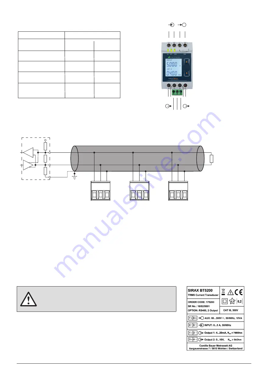
5.6 Modbus interface RS485

Via the optional Modbus interface measurement data may be provided for a superior system. 

MASTER

+3.3 / +5V

Rx/Tx+,A

RS485 Bus

Rs

Rt

Rs

Rx/Tx-,B

GND

1)

Rt

A B G

A B G

A B G

The signal wires (A, B) have to be twisted. G can be connected via a wire or via the cable screen. In disturbed environments shielded cables must 
be used. To avoid the possibility of loop currents, an Earth connection should be made at one point on the bus. Supply resistors (Rs) have to be 
present in bus master (PC) interface. Stubs should be avoided when connecting the devices. A pure daisy chain network is ideal.
You may connect up to 32 Modbus devices to the bus. A proper operation requires that all devices connected to the bus have equal 
communication settings (baud rate, transmission format) and unique Modbus addresses. 
The bus system is operated half duplex and may be extended to a maximum length of 1200 m without repeater.

5.5 Connection Diagram

1) One ground connection only. This is 

possibly made within the master 
(PC).

Rt: Termination resistors: 120 Ω each for 

long cables (> approx. 10 m)

Rs: Bus supply resistors, 
  390 Ω each

Label version

Before commissioning you have to check if the connection data of the device 
match the data of the plant.
If so, you can start to put the device into operation by switching on the power 
supply and the measurement inputs.

6. Commissioning

Connection

5
6

I/P ~
I/P ~

AUX

7
8

1
2

3
4

Measuring input

Auxilliary power supply

Measuring output - 1

Measuring output - 2

Terminal details

~

+

AUX ~-

O/P1
O/P1

+

-

O/P2
O/P2

+

-


A
B
G

Modbus

5 6

7 8

~ ~

~ ~

-

+

1

-

+

-

+

2

3 4

A B G

RS485

Input I

AUX

Output-1

Output-2

Summary of Contents for SIRAX BT5200

Page 1: ...le Bauer Metrawatt AG Aargauerstrasse 7 CH 5610 Wohlen Switzerland Tel 41 56 618 21 11 Fax 41 56 618 21 21 info cbmag com www camillebauer com Operating Instructions SIRAX BT5200 Transducer for AC cur...

Page 2: ...For the perfect and safe operation of the device proper transport and storage as well as professional assembly installation handling and maintenance are required Disclaimer of liability The content of...

Page 3: ...ud Rate 14 7 1 3 3 RS 485 Parity Selection 14 7 1 4 Output Type Selection 15 7 1 4 1 Output 1 Type selection 15 7 1 4 2 Output 2 Type Selection 15 7 1 5 Input parameter selection 16 7 1 5 1 End value...

Page 4: ...instructions SIRAX BT5200 Operating Instructions SIRAX BT5200 Product Brochure SIRAX Transducers series 2 Safety notes Device may only be disposed in a professional manner The installation and commis...

Page 5: ...drawing BT5200 See section 10 Any mounting position is possible Device may be clipped onto a top hat rail according EN 50022 4 2 Demounting of the device Disassembly of the device requires that all co...

Page 6: ...operating instructions Attention Danger to life Please note 5 2 Cross sections and tightening torques Terminals 1 8 Single wire 4 0mm2 or multiwire with end splices 2 x 2 5mm2 Torque 0 5 0 6Nm rsp 4...

Page 7: ...ion requires that all devices connected to the bus have equal communication settings baud rate transmission format and unique Modbus addresses The bus system is operated half duplex and may be extende...

Page 8: ...LED continuous ON O P 1 Output 1 voltage Green LED continuous ON Output 1 current Red LED continuous ON O P 2 Output 2 voltage Green LED continuous ON Output 2 current Red LED continuous ON Table 1 Me...

Page 9: ...entered prompt for second digit Denotes that digit will be flashing Pressing the Down key will scroll the value of the second digit from 0 through to 9 the value will wrap from 9 round to 0 Pressing t...

Page 10: ...he operation to the next digit and set the first digit in this case to 4 Enter New Change Password first digit entered prompting for second digit Denotes that digit will be flashing Pressing the Down...

Page 11: ...try stage Pressing the Up key will confirm New Password and advance to the Potential Transformer parameter selection section 7 1 2 Pressing the Down key will enter the New Change CT Primary value edit...

Page 12: ...Down key will scroll the value of the third digit from 0 through to 9 the value will wrap from 9 round to 0 Pressing the Up key will advance the operation to the next digit and set the third digit in...

Page 13: ...New changed Address value Denotes that digit will be flashing Pressing the Down key will scroll the value of the second digit from 0 through to 2 the value will wrap from 2 round to 0 Pressing the Up...

Page 14: ...will confirm the present value as Baud rate and advance to the Parity Selection secti on 7 1 3 3 RS 485 Baud Rate confirmation Pressing Down key will be re enter into the Baud Rate Edit mode Pressing...

Page 15: ...e output 1type edit mode and scroll between voltage and current Pressing Up key will confirm the present type for Output 1 and advance to the Output 2 type selection section 7 1 4 2 Output 1 Type conf...

Page 16: ...Pressing the Up key will advance the operation to the next digit and set the second digit in this case to 5 Enter New Change End value of Input second digit entered prompting for third digit Denotes...

Page 17: ...sing the Up key will advance the operation to the next digit and set the second digit in this case to 0 Enter New Change Start value of Input second digit entered prompting for third digit Denotes tha...

Page 18: ...Elbow value of the Input and advance to the Output parameter selection section 7 1 6 New Change Elbow value of the Input Denotes that digit will be flashing Pressing the Down key will scroll the value...

Page 19: ...y will advance the operation to the New Changed Elbow value of the Input and set the fourth digit in this case to 0 New changed Elbow value of the Input confirmed Pressing the Down key will re enter t...

Page 20: ...digit from 0 through to 9 the value will wrap from 9 round to 0 depending on the set End value of Output Pressing the Up key will advance the operation to the New Changed Start value of the Output 1...

Page 21: ...ange Elbow value of the Output 1 third digit entered prompting for fourth digit denotes that digit will be flashing Pressing the Down key will scroll the value of the fourth digit from 0 through to 9...

Page 22: ...second digit in this case to 1 Enter New Change Start value of the Output 2 second digit entered prompting for third digit Denotes that digit will be flashing Pressing the Down key will scroll the va...

Page 23: ...case to 5 Enter New Change Elbow value of the Output 2 second digit entered prompting for third digit Denotes that digit will be flashing Pressing the Down key will scroll the value of the third digi...

Page 24: ...connection and the programming connection at the transducer 7 3 Programming via the RS485 Modbus interface Follow the subsequent steps to program the transducer via the RS485 interface and Modbus Schr...

Page 25: ...tered during normal operation if for example the specified ambient conditions are not met 8 3 Cleaning The display and the operating keys should be cleaned in regular intervals Use a dry or slightly m...

Page 26: ...g Output Y Single or Optional Dual Output type Load independent DC Voltage or DC Current Onsite selectable through DIP switches Programming Range 0 4 20 mA 0 2 10 V Output burden with DC current outpu...

Page 27: ...ed Value 1 Auxiliary supply frequency Rated Value 1 Output Load Rn 7 5 V Y2 1 With DC current output signal Rn Y2 1 mA 1 With DC Voltage output signal Additional Error Temperature influence 0 2 10 K S...

Page 28: ...Acceleration 3 x 50g 3 shocks in each direction EN 60068 2 1 2 3 Cold Dry Damp heat EN 61000 4 2 3 4 5 6 EN 55011 Electromagnetic compatibility 10 Dimensional drawings 43 5mm 106 5mm 65 5mm 11 Interf...

Page 29: ...with valid parity and error check but which contains some other error e g Attempt to set floating point variable to an invalid value The response generated will be Function code 0x80 01 Illegal functi...

Page 30: ...NONE 2 2 2400 EVEN 1 10 9600 EVEN 1 3 2400 ODD 1 11 9600 ODD 1 4 4800 NONE 1 12 19200 NONE 1 5 4800 NONE 2 13 19200 NONE 2 6 4800 EVEN 1 14 19200 EVEN 1 7 4800 ODD 1 15 19200 ODD 1 40019 Password R T...

Reviews: