background image

14

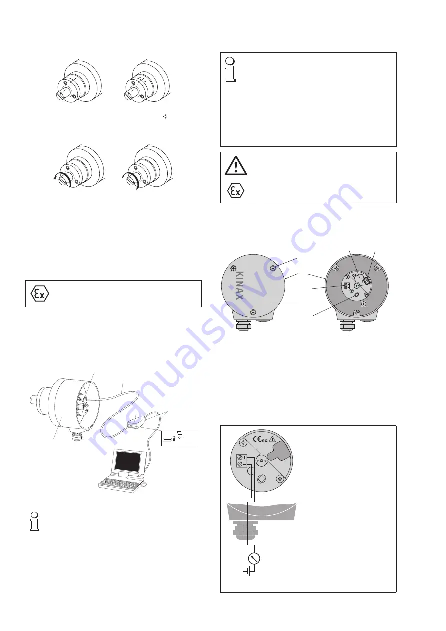
7. Adjusting the angle

Angular  position  transmitters  of  the  KINAX  WT  717  range  do  not  require 
a mechanical zero position mark (however, this is made if required by the 
customer, see Fig. 1).

Fig. 1. 
Left:  

for rotation transmitters with the range of 0 to ... 

º,

Right: 

for rotation transmitters with V characteristic ranges.

Fig. 2. 
Sense of rotation seen from the shaft side:
Left: counterclockwise, right: clockwise.

During installation the shaft of the transmitter can be coupled to the object 
to be measured in any position. Adjust the shaft angle as follows with the 
2W2 configuration software:

1.  Remove the cover (3.1 in Fig. 4). Remove the rubber cover  (5.1) to gain 

access  the  programming  connector  (5),  (see  section    “8.1  Connecting 
transmitter”).  Connect  the  KINAX  WT  717  to  the  programming  device 
according to Fig.  3. Start the 2W2 configuration software. If necessary, 
configure the device with the required measuring range data.

The angular position transmitter must only be programmed 
outside of the Ex area!

2.  Place the measuring device in a defined position (prefereably the zero 

position).

3.  Select the 

“Adjustment”

 menu item under 

“SERVICE”

 in the configuration 

software. In the 

“Mechanical position”

 window enter the current angle 

of the measuring device and then select 

“Adjust”.

 The measuring device 

is now configured for the defined angle.

Programming
connector

Interface

KINAX WT717

PK 610

Ancillary cable

OFF

ON

OFF: Power supply
by measuring output
(Fig. 5)

ON: Power supply
provided by PC

Fig. 3. Connection diagram programming

If you programm the KINAX WT717 with a connected power 
supply, then the switch on the interface PK610 must be im

-

perative switched to OFF. If this is ignored, this can lead to the 
destruction of the device.

8. Electrical connections

Screw terminals 

and 

cable glands

 are provided for making the electrical 

connections to the transmitter. 

Note that, …

…  the data required to carry out the prescribed measurement 

must correspond to those marked on the nameplate of the 
KINAX WT 717 (measuring) input, measuring output, power 
supply)!

…  the total loop resistance connected to the output (receiver 

plus leads) 

does not 

exceed the maxi mum permissible value 

R

ext.

! See 

“Measuring output”

, section “5. Technical data”!

…  twisted cores must be use for the measured variable input 

and output leads and routed as far away as possible from 
power cables!

In all other respects, observe all local regulations when selecting 
the type of electrical cable and installing them!

In the case of

 “Intrinsically safe” 

explosion-proof versions, 

the  supplementary  information  given  on  the  EC-Type-
Examination  Certificate,  the  EN  60  079-14  and  also  local 
regulations applicable to electrical installations in explosion 
hazard areas must be taken into account!

8.1 Connecting transmitter

To connect the transmitter, first remove the 3 screws (3.2), and remove the 
cover (3.1).  The maximum wire gauge the terminals (4.1) can accept is 1.5 mm

2

.

(3.2)

(3.1)

(3)

(4)

(4.1)

(4.2)

(5)

(5.1)

Fig. 4. Rear (3) with terminals (4.1) and cable glands (4).
Left: 

with cover (3.1) closed.

Right: 

without cover (3.1).

Undo the gland nut and remove the pinch ring and seal from the gland opening. 
Place these parts over the cable in the correct order and pass the end of the 

cable through the gland hole into the rear of the transmitter.

Strip the insulation from a suitable length of the leads and connect them to 
the terminals (4.1) according to Fig. 5.
Then fit the gland seal, pinch ring and nut. Tighten the gland nut and replace 
the cover.

R

ext

– +

+

H

H   = 

DC

 power supply 


H = 12…33 V


resp. H = 12…

30

 V  with 

Ex


version

R

ext

 =  External resistance

Fig. 5. Connection diagram.

Summary of Contents for KINAX WT 717

Page 1: ...ngle de rotation KINAX WT717 Operating Instructions Transmitter for angular position KINAX WT 717 Руководство по эксплуатации Измерительный преобразователь угла поворота KINAX WT 717 Camille Bauer Metrawatt AG Aargauerstrasse 7 CH 5610 Wohlen Switzerland Phone 41 56 618 21 11 Fax 41 56 618 21 21 info cbmag com www camillebauer com II 2 G ...

Page 2: ...tmo sphäre Öle Säure Gase Dämpfe Strahlungen etc bei der Montage vorhanden sind 1 4 Reparaturen und Änderungen ReparaturenundÄnderungensindausschliesslichdurchden Hersteller auszuführen Bei unsachgemässen Eingriffen in das Gerät erlischt der Garantieanspruch Änderungen die zurVerbesserungdesProduktesführen behaltenwirunsvor 1 5 Entsorgung Geräte und Bestandteile dürfen nur fachgerecht und nach län...

Page 3: ...htungen 5 8 Betrieb in explosionsgefährdeten Bereichen Gasexplosions schutz Kennzeichnung Ex ia IIC T6 Gb Normkonformität ATEX EN 60079 0 2012 EN 60079 11 2012 Zündschutzart ia Temperaturklasse T6 Gruppe nach EN 60079 0 2012 II Der Einsatz in anderen explosionsgefährdeten Bereichen ist nicht zulässig An Betriebsmittel die in explosionsgefährdeten Bereichen eingesetzt werden darf keine Veränderung ...

Page 4: ...717 mit einer angeschlos senenHilfsenergie mussderSchalteraufdemInterfacePK610 zwingend auf OFF geschaltet sein Wird dies nicht beachtet kann dies zur Zerstörung des Gerätes führen 8 Elektrische Anschlüsse Zum Anschliessen der elektrischen Leitungen hat der Mess umformer Schraubklemmen und Stopfbuchsen Es ist zu beachten dass die Daten die zur Lösung der Mess aufgabe erforderlich sind mit denen au...

Page 5: ...treiben sind die Vorschriften gemäss EN60079 14 das Gerätesicherheitsgesetz die allgemein anerkannten Regeln der Technik und diese Betriebsanleitung massgebend 11 Wartung Das Gerät arbeitet wartungsfrei Reparaturen dürfen nur von autori sierten Stellen ausgeführt werden 12 Aufschlüsselung der Varianten Erklärung der Bestell Ziffern 1 bis 13 Beschreibung Bestell Code 1 Ausführung des Messumformers ...

Page 6: ...Übersetzung 60 1 P Übersetzung 64 1 Q Übersetzung 72 1 R Übersetzung 75 1 S Übersetzung 80 1 T Übersetzung 100 1 U Übersetzung 120 1 V Übersetzung 144 1 W Beschreibung Bestell Code 13 Zusatzgetriebe 150 1 bis 1600 1 Ohne Getriebe 0 Übersetzung 150 1 1 Übersetzung 160 1 2 Übersetzung 180 1 3 Übersetzung 200 1 4 Übersetzung 240 1 A Übersetzung 250 1 B Übersetzung 300 1 C Übersetzung 330 1 D Übersetz...

Page 7: ...ue de l appareil correspondent avec le réseau de tension l appareil est en parfait état et l absence d atmosphère explosible d huiles d acides de gaz de vapeurs de rayonnement etc pendant le montage est assurée 1 4 Réparations et modifications Les réparations et les modifications doivent uniquement être effectuées par le fabricant En cas d intervention inappropriée sur l appareil la garantie n est...

Page 8: ...mpérature ambiante minimale admissible est de 40 C Température lors du transport ou du stockage 40 à 80 C Altitude 2000 m max Résistance aux vibration 0 200 Hz sans engrenage 10 g permanent 15 g pendant 2 h 0 200 Hz 5 g permanent 10 pendant 2 h Choc 3x50 g sur 10 chocs dans toutes les directions 5 8 Exploitation en zones explosives Protection contre les explosions de gaz Identification Ex ia IIC T...

Page 9: ...ammé en raccordant une énergie auxiliaire le commutateur sur l interface PK610 doit être impérativement réglé sur OFF Si ceci n est pas respecté ladestructiondel appareilenseralaconséquence 8 Raccordements électriques Le convertisseur de mesure comporte des bornes et presse étoupes pour le raccordement des câbles électriques Veiller en plus que les caractéristiques techniques qui permettent de rés...

Page 10: ...r variantes avec protection contre les explosions Les réglementations conformément à la norme EN60079 14 la loi sur la sécurité des appareils les règles techniques généralement reconnues ainsi que ce mode d emploi sont décisifspourlamiseenplaceetl exploitation Afind atteindre le type de protection IP requis conformément à la norme EN60529 1991 il est impàratif de monter correctement les presse éto...

Page 11: ...pport d engrenage 50 1 O Rapport d engrenage 60 1 P Rapport d engrenage 64 1 Q Rapport d engrenage 72 1 R Rapport d engrenage 75 1 S Rapport d engrenage 80 1 T Rapport d engrenage 100 1 U Rapport d engrenage 120 1 V Rapport d engrenage 144 1 W Description Article No 13 Engrenage 150 1 à 1600 1 Sans engrenage 0 Rapport d engrenage 150 1 1 Rapport d engrenage 160 1 2 Rapport d engrenage 180 1 3 Rapp...

Page 12: ...fications shall exclusively be car ried out by the manufacturer In case of any tampering with the device the guaranty claim shall lapse We reserve the right of changing the product to improve it 1 5 Disposal The disposal of devices and components may only be realised in accordance with good professional practice observing the country specific regulations 1 6 Transport and storage Transport and sto...

Page 13: ... every 10 impulses in all 3 axes 5 8 Operation in potentially explosive environments Gas explosion prevention Labeling Ex ia IIC T6 Gb Conform to standard ATEX EN 60079 0 2012 EN 60079 11 2012 Type of protection ia Temperature class T6 Group according to EN 60079 00 2012 II The operation in other explosive atmospheres is not permissible It is not permissible to make any alteration to equipment tha...

Page 14: ...can lead to the destruction of the device 8 Electrical connections Screw terminals and cable glands are provided for making the electrical connections to the transmitter Note that the data required to carry out the prescribed measurement must correspond to those marked on the nameplate of the KINAX WT 717 measuring input measuring output power supply the total loop resistance connected to the outp...

Page 15: ...er Code 1 Version Standard 717 1 Ex ia IIC T6 CENELEC ATEX 2 Sea water version 3 Sea water version with gear 4 Sea water version Ex ia IIC T6 Gb ATEX 5 Sea water version with gear Ex ia IIC T6 Gb ATEX 6 2 Angle range mechanically Angle range up to 50 1 Angle range 50 350 2 3 Sense of rotation Sense of rotation clockwise 0 Sense of rotation counter clockwise 1 For V characteristic 2 Lines 1 and 2 N...

Page 16: ...ransformation 240 1 A Transformation 250 1 B Transformation 300 1 C Transformation 330 1 D Transformation 360 1 E Transformation 375 1 F Transformation 400 1 G Transformation 450 1 H Transformation 480 1 J Transformation 500 1 K Transformation 550 1 L Transformation 600 1 M Transformation 660 1 N Transformation 720 1 O Transformation 750 1 P Transformation 800 1 Q Transformation 880 1 R Transforma...

Page 17: ...е изменений Правомосуществлятьремонтивноситьизмененияобладает исключительноизготовитель Принесанкционированномвмеша тельствевустройствоправонагарантийныйремонтутрачивается Изготовительоставляетзасобойправонавнесениеизменений ведущих к улучшению характеристик изделия 1 5 Утилизация Утилизацияустройствикомплектующихчастейдолжнапроизво дитьсяпоправиламивсоответствииспредписаниямиместного законодатель...

Page 18: ...40 до 80 C Рабочая высота макс 2000 м Устойчивость к вибрации 0 200 Гц без дополнительного привода 10 g длительно 15 g в течение 2 ч 200 500 Гц 5 g длительно 10 g в течение 2 ч Удароустойчивость 3 50 g по 10 ударов в любом направлении 5 8 Эксплуатация во взрывоопасных зонах Защита от взрыва газа Обозначение Ex ia IIC T6 Gb Согласованность стандартов ATEX EN 60079 0 2012 EN 60079 11 2012 Уровень вз...

Page 19: ...змерительный выход Рис 5 Вкл ON Вспомогательное питание подается от ПК Дополнительный кабель Программируемое подключение Интерфейс ПрограммированиеустройстваKINAXWT717осуществляетсясподачей вспомогательногопитания приэтомвыключательнаинтерфейсеPK610 следуетустановитьвположениеВыкл OFF Несоблюдениеэтоготре бования может привести к поломке устройства 8 Электрические подключения Дляподключенияизмерит...

Page 20: ...щиепризнанныетехнические правилаитребованияданногоруководствапоэксплуатации 11 Техническое обслуживание Устройствонетребуеттехническогообслуживания Ремонтследуетосуществлятьв авторизованных сервисных центрах 12 Различные варианты Расшифровка кодов комплектации с 1 по 13 Описание Код поставки 1 Комплектация измерительного преобразователя Стандартная 717 1 Ex ia IIC T6 CENELEC ATEX 2 Комплектация ус...

Page 21: ...25 1 J Передача 30 1 K Передача 32 1 L Передача 36 1 М Передача 40 1 N Передача 50 1 O Передача 60 1 P Передача 64 1 Q Передача 72 1 R Передача 75 1 S Передача 80 1 T Передача 100 1 U Передача 120 1 V Передача 144 1 W Описание Код поставки 13 Дополнительный редуктор 150 от 1 до 1600 1 Без редуктора 0 Передача 150 1 1 Передача 160 1 2 Передача 180 1 3 Передача 200 1 4 Передача 240 1 А Передача 250 ...

Page 22: ...22 13 Konformitätserklärung Certificat de conformité Declaration of conformity Декларация соответствия ...

Page 23: ...23 ...

Page 24: ...24 ...

Reviews: