


M6
B
A
GND
LINE 1A-F
2
10
4
11
CX
3
B
A
GND
Pa
g
e
1414
- M
an
u
al
c
od
e
FA
0
0
13
5
-E
N
FA
0
0
13
5
-E
N
- ve
rs
.
22
- 0
1/2
0
17 - © C
am
e S
.p.
A
. -
The contents of this manual may be changed, at any time, and without notice.
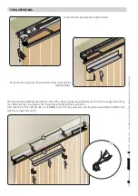
Option 1
Option 2
There are two possible points to pass the power-supply and accessory-control cables through: either on the anchoring base
through the existing slots (option 1), or on the end cap which features pre-shaped apertures (option 2).
Connect the ground to both gearmotors.
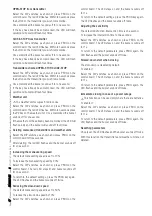
Command and control devices
AF card
CRP - Came Remote Protocoll.
Connection to the home-automation
system.
RSE card
OPEN-STOP function (NO contact)
CLOSE-STOP function (NO contact)
⚠
If the PARTIAL OPENING function is activated via a dip-switch on the button connected to 2-3, then the button connected
to 2-4 will automatically operate as a sequential OPEN-STOP-CLOSE-STOP command.
⚠
If MAINTAINED ACTION is activated via dip-switches, the two buttons will operate as automatically OPEN and CLOSE,
respectively.
⚠
When the MAINTAINED ACTION function is active, the PARTIAL OPENING function cannot be set.
LEFT
-
HAND
MOTOR
RIGHT
-
HAND
MOTOR
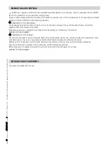
The AF and RSE cards must be fitted
into the control board AFTER CUTTING
OFF THE MAINS POWER.
N.B.: the basic control board recognises
them only when it is powered up.


