45°
45°
ENGLISH
P
age
1
3
1
3
- M
a
nu
a
l C
o
d
e:
1
1
9
G
V
2
2
1
1
9
G
V22 v
e
r.
2
.1
2.
1
12
/2
0
11
© C
A
M
E
c
a
n
ce
lli a
u
to
mati
ci
S
.p.
a
. - T
h
e d
a
ta a
n
d i
n
fo
rm
ati
o
n
i
n
thi
s ma
nu
a
l ma
y b
e c
h
a
n
g
e
d at a
n
y time a
n
d with
o
ut o
b
lig
a
ti
o
n
o
n
the p
a
rt
of C
a
me C
a
n
ce
lli A
u
to
mati
ci
S
.p.
a
. to n
o
tify s
a
id
c
h
a
n
g
e
s.
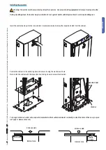
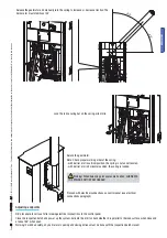
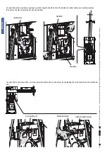
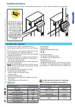
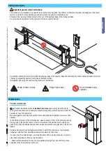
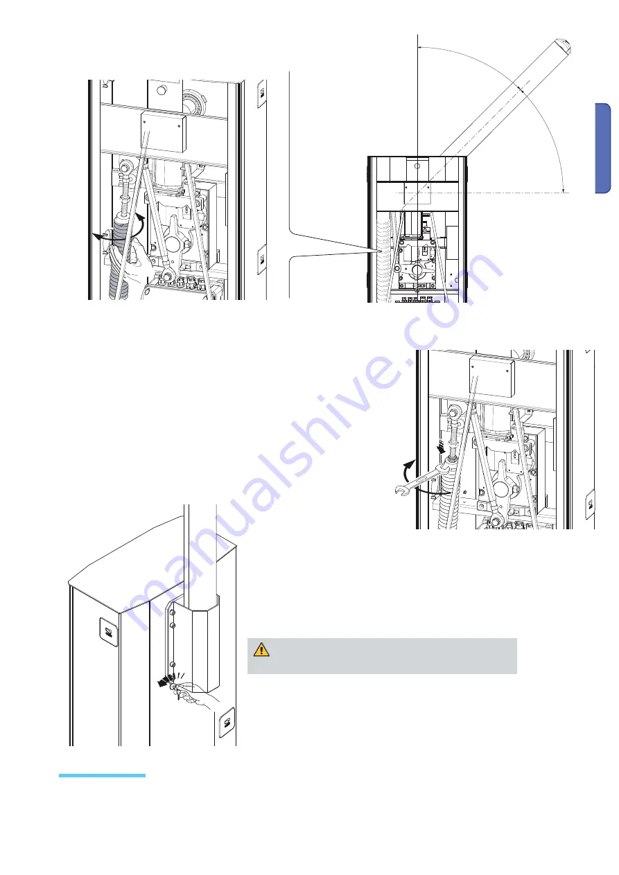
Release the gearmotor and manually turn the spring to increase or decrease traction. The
barrier arm must stabilise at 45°.
NB: procedure to carry out after making electrical connections to the control panel.
Close the inspection hatch and power up the system. Activate the arm to check whether it is parallel to the road surface when close and
at about 89° when open.
Warning! For added safety, any barrier arm opening and closing actions must be done with the inspection hatch closed!
Adjusting endpoints
Lock the rod securing nut on the spring. alla molla.
Relock the gearmotor.
Note: Check proper working order of the spring:
- with barrier arm in vertical position, the spring is not under tension.
- with barrier arm in horizontal position, the spring is loaded.
Warning! When balancing procedures are fi nished, LUBRICATE
THE SPRINGS WITH SPRAY GREASE!
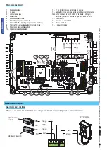
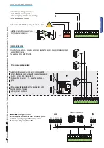
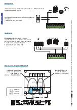
Proceed with electrical connections on control panel (see electrical
connections paragraph)
Summary of Contents for G6500
Page 29: ...B a r r i e r l i n e G6500 SERIES GARD INSTALLATION MANUAL STREET BARRIERS English EN 9 1...
Page 85: ...B a r r i e r l i n e G6500 GARD RU 9 RU...
Page 94: ...362 mm 10 10 119 G V 22 119 G V 22 2 1 2 1 12 2011 2011 CAME cancelli automatici s p a 6500...
Page 96: ...12 12 119 G V 22 119 G V 22 2 1 2 1 12 2011 2011 CAME cancelli automatici s p a...
Page 107: ...CA ME 2 3 2 3 119 G V 22 119 G V 22 2 1 2 1 12 2011 12 2011 CAME cancelli automatici s p a...
Page 111: ...27 27 119 G V 22 119 G V 22 2 1 2 1 12 2011 12 2011 CAME cancelli automatici s p a...

