


p.
2
1
2
1
- M
a
n
u
a
l c
o
d
e:
FA
00
13
2
-
E
N
-E
N
v
.
2
2
08
/2
01
6
© C
A
M
E
C
a
n
ce
lli A
u
to
m
a
ti
ci
S
.p.
A
. - T
h
e d
a
ta a
n
d i
n
fo
rm
ati
o
n i
n
t
h
is
m
a
n
u
a
l m
ay b
e c
h
a
n
g
e
d at a
n
y time a
n
d wit
h
o
u
t n
o
ti
ce
.
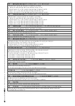
F 30
Opening slow-down speed
15 = Minimum speed / … / 40 = Maximum speed
Setting the boom's opening slow-down speed, calculated as a percentage.
⚠
Warning: the speed parameter fi elds vary depending on the type of boom:
- for jointed booms of 2 m, set the slow-down speed percentage to between 20 and 40;
- for booms of 4 m, set the slow-down speed percentage to between 20 and 30;
- for booms of 6 m and 8 m, set the slow-down speed percentage to between 15 and 40.
F31
Closing slow-down speed
15 = Minimum speed / … / 40 = Maximum speed
Setting the boom's closing slow-down speed, calculated as a percentage.
⚠
Warning: the speed parameter fi elds vary depending on the type of boom:
- for jointed booms of 2 m, set the slow-down speed percentage to between 20 and 40;
- for booms of 4 m, set the slow-down speed percentage to between 20 and 30;
- for booms of 6 m, set the slow-down speed percentage to between 15 and 30;
- for booms of 8 m, set the slow-down speed percentage to between 15 and 20;
F33 Calibration
speed
20 = 20% of the travel (minimum) / … / 40 = 40% of the travel (maximum)
Setting the boom's travel automatic calibration, calculated as a percentage
F34
Boom travel sensitivity
10 = maximum sensitivity / … / 100 = minimum sensitivity (default)
Adjusting obstruction detection sensitivity during boom travel.
F35 Slow-down
sensitivity
10 = maximum sensitivity / … / 100 = minimum sensitivity (default)
Adjusting obstruction detection sensitivity during slow-down.
F37
Opening slow-down point
40 = 40% of the travel / … / 60 = 60% travel
Percentage adjustment of the boom's total travel, from the beginning of the opening slow-down point.
Warning! The percentage varies depending on the boom type:
- for jointed booms of 2 m and 4 m, set the percentage to between 40 and 60;
- for booms of 6 m and 8 m, set the percentage to between 60 and 70.
F38 Closing slow-down point
20 = 20% of the travel /… / 75 = 75% of the travel
Establishing the total travel percentage, from the beginning of the closing slow-down point.
Warning! The percentage varies depending on the boom type:
- for jointed booms and 2-meter booms, set the speed percentage to between 20 and 40;
- for 2 m booms, set the percentage to between 40 and 60;
- for 6 m booms, set the percentage to between 60 and 70;
- for 8 m booms, set the percentage to between 65 and 75;
F 49
Enabling serial connections
0 = Deactivated (
default
) / 1 = Paired / 2 = Alternate
To enable paired or alternate operation.
F50 Save
data
0 = Deactivated (
default
) / 1 = Activated
To save system users and settings in memory roll.
This function only appears if the memory roll has been fi tted into the control panel.
F51 Read data
0 = Deactivated (
default
) / 1 = Activated
To upload the data saved in the memory roll into the control panel.
This function only appears if the memory roll has been fi tted into the control panel.
F52
Passing settings in paired/alternating mode
0 = Deactivated (
default
) / 1 = Activated
Loading parameters of the MASTER barrier into the SLAVE barrier.
This function appears only if function F 49 is set to either PAIRED or ALTERNATE.
F60 Sleep
Mode
To reduce the amount of energy consumed by the stand-by photocells.
F61 Pre-fl
ashing
0 = when opening and closing (default) / 1 = only when closing / 2 = only when opening
After an opening or closing command, the fl ashing light connected to 10-E1m fl ashes before starting the maneuver.
For setting the time, see function F 21.


