background image

L

190

46

101

RV118I

RV118A

RV118N

RV118M

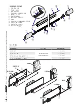
TMFW - TMFWN

TMF6W - TMF6WN

RV117H

Pa

g.


22

 - C

od

ic

e m

an

ua

le 

FA

017

53

-I

T

FA

017

53

-I

T

  - 0

1/

20

22 - © C

am

e S

.p

.A

. - I c

on

te

nu

ti d

el m

an

ua

le s

on

o d

a r

ite

ne

rs

i s

us

ce

tti

bi

li d

i m

od

ifi

ca i

n q

ua

ls

ia

si m

om

en

to s

en

za o

bb

lig

o d

i p

re

av

vis

o

IMPORTANTI ISTRUZIONI DI SICUREZZA PER L’INSTALLAZIONE

ATTENZIONE! L’INSTALLAZIONE NON CORRETTA PUÓ CAUSARE GRAVI DANNI, SEGUIRE TUTTE LE ISTRUZIONI DI INSTALLAZIONE

IL PRESENTE MANUALE È DESTINATO ESCLUSIVAMENTE A INSTALLATORI PROFESSIONALI O A PERSONE COMPETENTI

LEGENDA

  Parti da leggere con attenzione.

  Parti riguardanti la sicurezza.

  Cosa comunicare all’utente.

RIFERIMENTI NORMATIVI

Il prodotto è conforme alle direttive di riferimento vigenti.

DESCRIZIONE

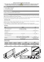
Questo prodotto è progettato e costruito da Came S.p.A. in conformità alle vigenti norme di sicurezza, ed è certificato 
(PR&S n.04.363) per applicazione in verticale e orizzontali.
Il bordo sensibile è costituito da un profilo di supporto in alluminio e da un profilo e due tappi in gomma. All’interno del profilo 
in gomma ci sono due meccanismi a leve snodate unite da una fune in acciaio (ø 1,3 mm).

Destinazione d'uso

Il bordo sensibile di sicurezza è destinato alla protezione dal rischio di schiacciamento e di intrappolamento. La rilevazione 
avviene per contatto su tutta la lunghezza del bordo, compresi i tappi.

 Ogni installazione e uso difformi da quanto indicato nel seguente manuale sono da considerarsi vietate.

 Il presente manuale è destinato solamente al personale tecnico professionale o persona qualificata per l’installazione.

Dati tecnici

Tipo

DFWN

DFI

Grado di protezione (IP)

54 (fissato in verticale)

44 (fissato in orizzontale)

56

Alimentazione (V)

-

12-24 AC / DC

Fusibile (mA)

-

630

Temperatura di esercizio (°C)

-20 ÷ +55

-20 ÷ +55

Classe dell'apparecchio

II

II

 Materiali

Profilo in gomma termoplastico CCA 48SHA

Tappi in gomma termoplastico SEBS 60SHA

Leve snodate POM

Fune in acciaio

Scatola in 

tecnopolimero isolante 

autoestinguente

Dimensioni (mm)

DFWN1500

DFWN1500N

DFWN1700

DFWN1700N

DFWN2000

DFWN2000N

DFWN2500

DFWN2500N

DFWN

(TMFW)

(TMFWN)

DFWN

(TMF6W)

(TMF6WN)

1500

1700

2000

2500

4000 max

6000 max

Summary of Contents for DFWN2000

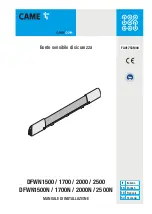
Page 1: ...IT Italiano EN English FR Fran ais RU P Bordo sensibile di sicurezza DFWN1500 1700 2000 2500 DFWN1500N 1700N 2000N 2500N MANUALE DI INSTALLAZIONE FA01753M04...

Page 2: ...e tappi in gomma All interno del profilo in gomma ci sono due meccanismi a leve snodate unite da una fune in acciaio 1 3 mm Destinazione d uso Il bordo sensibile di sicurezza destinato alla protezione...

Page 3: ...tipo Collegamento Tipo cavo Sezione cavo A C NC FROR CEI 20 22 CEI EN 50267 2 1 2 X 0 5 mm2 B C NO NC 3 X 0 5 mm2 C C NC Alimentazione 12 24 V 4 X 0 5 mm2 D C NC Resistiva 8 2 KOhm 2 X 0 5 mm2 Compone...

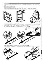
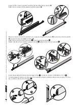
Page 4: ...unghezza nominale LN della zona da proteggere Attenzione Nelle installazioni verticali ridurre di 30 mm la lunghezza nominale LN per evitare il contatto con il suolo Forare il profilo con una punta di...

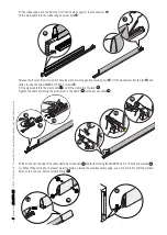
Page 5: ...tamicro con una leggera pressione verso il basso inserire il meccanismo nel profilo e fissarlo con le due viti UNI6955 3 9x13 Infilare la fune in acciaio nel foro del morsetto 11 e inserire il morsett...

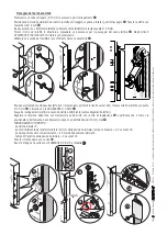
Page 6: ...gi predisposto Utilizzare una sonda per facilitare lo scorrimento del cavo nel profilo Posizionare il bordo sensibile sulle staffe con il meccanismo portamicro rivolto verso l alto forare sui lati de...

Page 7: ...1753 IT FA 01753 IT 01 2022 Came S p A I contenuti del manuale sono da ritenersi suscettibili di modifica in qualsiasi momento senza obbligo di preavviso Collegamento al modulo Wireless Collegamento a...

Page 8: ...DERE NELL AMBIENTE RISOLUZIONE DEI PROBLEMI Problema Possibile causa Verifiche e rimedi Il bordo non interviene Un cavo danneggiato Rivolgersi all assistenza l automazione non deve essere usata Il bor...

Page 9: ...Sensitive safety edge DFWN1500 1700 2000 2500 DFWN1500N 1700N 2000N 2500N INSTALLATION MANUAL EN English FA01753 EN...

Page 10: ...ber end caps The rubber edge houses two joined and jointed lever mechanism and one 1 3 mm steel cable Intended use The sensitive safety edge is made for preventing crushing or entrapment by gates Dete...

Page 11: ...ation Connection Cable type Cable section A C NC FROR CEI 20 22 CEI EN 50267 2 1 2 X 0 5 mm2 B C NO NC 3 X 0 5 mm2 C C NC Power supply 12 24 V 4 X 0 5 mm2 D C NC Resistive 8 2 KOhm 2 X 0 5 mm2 Main co...

Page 12: ...tablish the LN or nominal length of the area you with to protect Warning With vertical fittings reduce the LN by 30 to the edge from scraping the ground Use a 3 mm bt to drill the rail on either side...

Page 13: ...y gently pressing down fit the mechanism into the rail and fasten it using the two UNI6955 3 9x13 screws Fit the steel cable into the clamp hole 11 and fit the clamp into the lever 12 Tighten the cabl...

Page 14: ...help the cable along the rail Place the sensitive safety edge onto the braces with the micro switch holding mechanism facing up drill on either side of the rail using a 2 5 mm bit and fasten it using...

Page 15: ...Manual code FA 01753 E N FA 01753 E N 01 2022 Came S p A The contents of this manual may be changed at any time without prior notice Connecting to the wireless module Connecting to the 806TF 0060 outb...

Page 16: ...OUBLESHOOTING Problem Possible cause Checks and fixes The edge does not activate A cable is damaged Call for technical assistance the operator must not be used in the meantime The sensitive safety edg...

Page 17: ...Bord sensible de s curit DFWN1500 1700 2000 2500 DFWN1500N 1700N 2000N 2500N MANUEL D INSTALLATION FR Fran ais FA01753 FR...

Page 18: ...ux embouts en caoutchouc Le profil en caoutchouc contient deux m canismes leviers articul s unis par un c ble en acier 1 3 mm Utilisation pr vue Le bord sensible de s curit est une protection contre l...

Page 19: ...ype c ble Section c ble A F NF FROR CEI 20 22 CEI EN 50267 2 1 2 X 0 5 mm B F NO NF 3 X 0 5 mm C F NF Alimentation 12 24 V 4 X 0 5 mm D F NF R sistive 8 2 KOhms 2 X 0 5 mm Composants principaux 1 Embo...

Page 20: ...LN de la zone prot ger Attention En cas d application verticale r duire la longueur nominale LN de 30 mm pour viter tout contact avec le sol Percer le profil l aide d une m che d un diam tre de 3 mm...

Page 21: ...ssant l g rement vers le bas introduire le m canisme dans le profil et le fixer l aide des deux vis UNI6955 3 9x13 Faire passer le c ble en acier travers le 11 trou de la bride et introduire la bride...

Page 22: ...du c ble dans le profil Positionner le bord sensible sur les brides avec m canisme de support du micro interrupteur orient vers le haut percer sur les c t s du profil l aide d une m che d un diam tre...

Page 23: ...l FA 01753 F R FA 01753 F R 01 2022 Came S p A Le contenu du manuel est susceptible de subir des modifications tout moment et sans aucun pr avis Connexion au module sans fil Connexion au module metteu...

Page 24: ...DANS LA NATURE R SOLUTION DES PROBL MES Probl me Cause possible Contr les et rem des Le bord n intervient pas Un c ble est endommag S adresser l assistance ne pas utiliser l automatisme Le bord sensi...

Page 25: ...DFWN1500 1700 2000 2500 DFWN1500N 1700N 2000N 2500N RU FA01753 RU...

Page 26: ...Came S p A CAME S p A PR S 04 363 1 3 DFWN DFI IP 54 44 56 12 24 630 C 20 55 20 55 II II CCA 48SHA SEBS 60SHA POM DFWN1500 DFWN1500N DFWN1700 DFWN1700N DFWN2000 DFWN2000N DFWN2500 DFWN2500N DFWN RV11...

Page 27: ...ED8WS RIOCT8WS DFWN DFWN DFWN DFWN B D 806TF 0060 TX C 3 3 FA 01753 R U FA 01753 R U 01 2022 Came S p A A FROR CEI 20 22 CEI EN 50267 2 1 2 X 0 5 B 3 X 0 5 C 12 24 4 X 0 5 D 8 2 2 X 0 5 1 2 3 4 5 6 7...

Page 28: ...LP LG 1 2 140 L N L N CAM E LN LN 30 30 4 3 5 150 4 3 5 150 4 4 FA 01753 R U FA 01753 R U 01 2022 Came S p A LN LN 30 3 UNI6955 3 9x13 LG LN 285 DFWN1500 1700 2000 2500 140 LP LN 40...

Page 29: ...8 9 10 7 6 11 12 13 14 17 15 16 5 5 FA 01753 R U FA 01753 R U 01 2022 Came S p A UNI6955 3 9x13 11 12 13 14 15 UNI 6954 3 9 x 13 16 4 17...

Page 30: ...2 1 3 2 5 5 4 6 7 2 5 5 4 6 7 1 2 3 4 10 11 20 mm 8 9 6 6 FA 01753 R U FA 01753 R U 01 2022 Came S p A 10 4 3 9 DFWN1500 1700 2000 2500 2 5 UNI 6954 2 9x13 20 20 0 2 45 2 UNI6954 3 9x13 11...

Page 31: ...C NO C 12V NC NO C 2 C1 10 11 1 2 1 2 2 1 DFWN DFI IN1 IN2 NC NO C NC NO C DFWN RIOED8WS RIOCT8WS NC NO C NC NO C K K K 4 3 2 1 806TF 0060 TX DFWN 806TF 0060 RX 7 7 FA 01753 R U FA 01753 R U 01 2022 C...

Page 32: ...CAME S p A Via Martiri Della Libert 15 31030 Dosson di Casier Treviso Italy tel 39 0422 4940 fax 39 0422 4941 FA 01753 R U FA 01753 R U 01 2022 Came S p A 6...

Reviews: