CAMDEN Invision TAC Series Installation Manual Download Page 16

CV-TAC400 Installation Guide   |   

16  


File: CV-TAC400_IN_MAN__NF_REV6.doc 
Revised: September 2, 2014 
Part No: 40-82B113


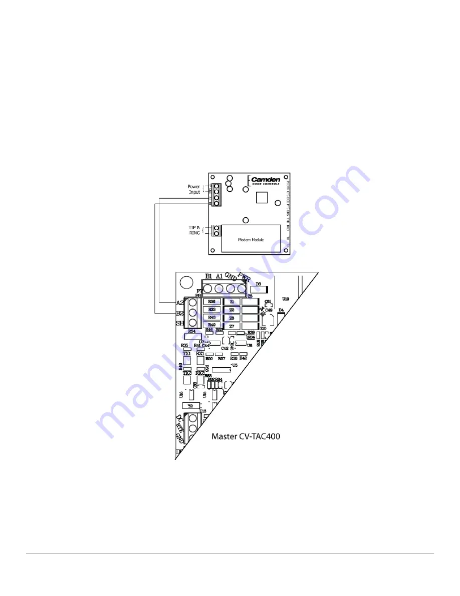
2.  Connect the Modem Module (Optional) 

An optional CV-TAC4M modem module is used to connect to a remote computer for programming the 
CV-TAC400. The remote computer must have a modem connection and calls the CV-TAC400. Details 
of programming the CV-

TAC400 are contained in the section “Remote Connection Using a Modem” 

When a modem connection is used the CV-TAC400 must be configured to use a shared phone line.  

The telephone line connected to the modem module may be the same telephone line used by the CV-
TAC400 to call the suites. 


Figure 4 - Optional Modem Module Connection 


Summary of Contents for Invision TAC Series

Page 1: ...CV TAC400 Telephone Access System Installation Guide...

Page 2: ...be regarded as affecting the validity of any trademark or service mark Disclaimer This book is provided as is without warranty of any kind either express or implied including but not limited to perfo...

Page 3: ...tware for the Modem ____________ 21 Setting the Remote Modem __________________________________ 23 Starting a Connection _______________________________________ 24 RS485 to USB Converter _____________...

Page 4: ..._65 20 Uploading Saved Information into the CV TAC400 __________66 Basic Master with Slave Unit ________________________________68 Hardware Connections ______________________________________ 68 1 Conn...

Page 5: ...s Client Software ____________98 12 Establishing a Connection with the CV TAC400 ____________99 Remote Connection Using a Modem __________________________ 99 Configuring the SFTD5202 Software for the...

Page 6: ...building is provided Elevator access may be controlled through any device i e Entry Phones Card Readers or Receivers in a variety of practical applications For example a visitor may call the suite ow...

Page 7: ...CV TAC400 Installation Guide 7 File CV TAC400_IN_MAN__NF_REV6 doc Revised September 2 2014 Part No 40 82B113 Figure 1 System Block Diagram...

Page 8: ...ied security screws Figure 2 Chassis Installation Connecting the Postal Lock Switch The common connection black wire is connected to one terminal of the postal lock terminal connector For a standard p...

Page 9: ...e controls for the speaker and the microphone are found on the rear of the front panel There are 2 volume control potentiometers located at the top center of the main PCB as shown below marked SPKv an...

Page 10: ...oose the Open Folder to View Files option if a window doesn t automatically open use the Windows Explorer to view the files on the CD b Select the db inst bat file with the right mouse button A menu w...

Page 11: ...lect the Open option A command window will open and an installation screen will appear Follow the directions on the screen If a security screen appears allow the installation to proceed d When the ins...

Page 12: ...ically open use the Windows Explorer to view the files on the CD b Select the db inst bat file with the right mouse button A menu will open up next to the file In that menu select the Run as administr...

Page 13: ...r 2 2014 Part No 40 82B113 In that menu select the Open option A command window will open and an installation screen will appear Follow the directions on the screen If a security screen appears allow...

Page 14: ...on telephone entry and card access or with multiple locations CV TAC400 provides unprecedented performance and value This application guide will cover the minimum steps required for you to install and...

Page 15: ...rrite Cubes To maintain compliance with emission standards the installer must install the supplied Ferrite Cubes on the Power and Telephone line connections Each connection is passed through its own c...

Page 16: ...e CV TAC400 The remote computer must have a modem connection and calls the CV TAC400 Details of programming the CV TAC400 are contained in the section Remote Connection Using a Modem When a modem conn...

Page 17: ...t connection to a computer is required for programming the CV TAC400 An RS485 to USB converter is used Connect the RS485 Converter as shown in Figure 5 Figure 5 RS 485 Connection to Computer 4 Connect...

Page 18: ...res you to login to the CV TAC400 locally via the front panel A Logging In To access the service mode the user must login with a password To do this follow the steps below Press and hold the 1 4 and 7...

Page 19: ...m you want to change and then use the 1 and 3 keys to increment or decrement that item The key moves the cursor right and at the end of the line moves down to the next line The key moves the cursor le...

Page 20: ...elect SFTD5202D from the list The main SFT5202 Windows Client Software window will be displayed 9 Establishing a Connection with the CV TAC400 The CV TAC400 is programmed via a Windows PC using an USB...

Page 21: ...omputer s operating system Different versions of the operating system will have different methods for determining the COM port The following discussion may not exactly match your particular system In...

Page 22: ...box select None j In the Stop Bits box select 1 k In the Echo box select Off l When you are done Save the settings by selecting the Save Settings button Initializing the Modem NOTE The modem will rem...

Page 23: ...These may be stored in a list so that they may be easily accessed Setting up a Remote Modem To add a remote site and its phone number and password to the list of sites follow the steps below a Start...

Page 24: ...lding Information box h Select OK to save the information or Close to exit without saving Starting a Connection Overview To communicate with a remote system via modem you must first start the connecti...

Page 25: ...t the Dial Up submenu The Dial Up form will be displayed e Select the remote site from the list of remote sites in the Building drop down list If the building is not in the list you may enter the info...

Page 26: ...nverter into an empty USB port on your computer A prompt to search the internet for a driver will pop up Select No not this time Press Next In the next window select Install from a list or specific lo...

Page 27: ...TAC400_IN_MAN__NF_REV6 doc Revised September 2 2014 Part No 40 82B113 Open the USBtoRS485_Drivers folder and select the CM20602 folder Press OK Select Next to start installing the driver The driver wi...

Page 28: ...ssion with the CV TAC400 Working Online with an RS485 Converter a Select the Session Menu b Select Open Session c Select OK when the session has finished loading 11 Open a Session with the CV TAC400 W...

Page 29: ...ect the remote CV TAC400 from the list you wish to communicate with c The CV TAC400 s data will be imported The download from the remote CV TAC400 can take up to 5 minutes 12 Changing the Greeting Mes...

Page 30: ...e Greeting Message field of the CV TAC400 you wish to change The field will open for editing You may change the text as required e When the editing is complete press the enter key or select anywhere e...

Page 31: ...Revised September 2 2014 Part No 40 82B113 b Select the Load the factory Default File into the computer submenu A file selection window will be displayed c Navigate the Explorer window to your CD Driv...

Page 32: ...ing the Greeting Message To change the Greeting Message perform the following steps g Select the View Edit Data Records Menu A list of submenus will be displayed h Select the Configuration Settings su...

Page 33: ...factory default file The information has been set to blank To add a suite merely select a blank record and enter the information a Select the View Edit Data Records Menu A list of submenus will be di...

Page 34: ...he number 6 was entered on a call to the suite The CV TAC400 maintains a list of PIN numbers and the associated Labels for the PIN Each PIN number must be between 5 and 9 digits long The PIN Code Labe...

Page 35: ...nter the new PIN code d In the Label edit box enter the associated Label e Select the Add button The PIN Code list grid will be updated f When all the changes have been completed select the SAVE butto...

Page 36: ...ion and create filename 18 Uploading Saved Information into the CV TAC400 A Working Online Using the RS485 Converter If you have been working online throughout this guide all you need to do is close t...

Page 37: ...le If you have been working online using the Modem Module you cannot simply close the session The new data must be exported to the CV TAC400 a Select the Export Data to an ELP520 s from the File Setup...

Page 38: ...re applying power to the unit 1 Connect the Telephone Line A dedicated telephone line is required TIP and RING connections are provided to allow connection to a telephone line Typically TIP is green a...

Page 39: ...module may be the same telephone line used by the CV TAC400 to call the suites Figure 9 Optional Modem Module Connection 3 Connect the Computer If you are not using the modem module above a direct co...

Page 40: ...er Installed in the CV TAC400 Connect the reader installed in the CV TAC400 to the connections in the CV TAC400 The minimum connections are power ground D0 and D1 Figure 11 Access Control Reader Conne...

Page 41: ...No 40 82B113 Figure 12 Door Strike Connection 6 Connect the Power Connect power 12 VDC to the CV TAC400 power connections on Port 1 Figure 13 Figure 13 Door and Power Connections 7 Set the Time and D...

Page 42: ...epeat the process From the main menu select 4 Date Time The Date and Time menu allows changing the CV TAC400 s date and time When the Date and Time menu is selected a display similar to the example fi...

Page 43: ...0 Slave 1 15 CV TAC400 Slave 2 16 CV TAC400 Slave 3 9 Starting the SFT5202 Windows Client Software The following instructions apply only if the default file locations were used in the software install...

Page 44: ...ialing information can be selected from that list Configuring the SFTD5202 Software for the Modem Overview Each time the modem is used the modem must be initialized Once the modem is initialized it ma...

Page 45: ...x select none i In the Parity box select None j In the Stop Bits box select 1 k In the Echo box select Off l When you are done Save the settings by selecting the Save Settings button Initializing the...

Page 46: ...ll have an associated password and phone number These may be stored in a list so that they may be easily accessed Setting up a Remote Modem To add a remote site and its phone number and password to th...

Page 47: ...Modem Information form will be displayed e Enter the Remote telephone number in the Telephone Number box f Enter the Remote modem Password in the ELP Default Password box g Enter the Building Identifi...

Page 48: ...ion a To start a connection to a remote system follow the steps below b Start the SFT5202 Windows Client Software c Select the Setup menu A list of submenus will be displayed d Select the Dial Up subm...

Page 49: ...nverter into an empty USB port on your computer A prompt to search the internet for a driver will pop up Select No not this time Press Next In the next window select Install from a list or specific lo...

Page 50: ...TAC400_IN_MAN__NF_REV6 doc Revised September 2 2014 Part No 40 82B113 Open the USBtoRS485_Drivers folder and select the CM20602 folder Press OK Select Next to start installing the driver The driver wi...

Page 51: ...ssion with the CV TAC400 Working Online with an RS485 Converter a Select the Session Menu b Select Open Session c Select OK when the session has finished loading 12 Open a Session with the CV TAC400 W...

Page 52: ...ect the remote CV TAC400 from the list you wish to communicate with c The CV TAC400 s data will be imported The download from the remote CV TAC400 can take up to 5 minutes 13 Changing the Greeting Mes...

Page 53: ...e Greeting Message field of the CV TAC400 you wish to change The field will open for editing You may change the text as required e When the editing is complete press the enter key or select anywhere e...

Page 54: ...Revised September 2 2014 Part No 40 82B113 b Select the Load the factory Default File into the computer submenu A file selection window will be displayed c Navigate the Explorer window to your CD Driv...

Page 55: ...CV TAC400 Installation Guide 55 File CV TAC400_IN_MAN__NF_REV6 doc Revised September 2 2014 Part No 40 82B113 e Select the factory Default file 500DIrs noname nouser and then select Open...

Page 56: ...Settings submenu The Configuration setting window will be displayed Do not change the CV TAC400 Address field at the top of the window c Select the Misc tab The miscellaneous tables will be displayed...

Page 57: ...oors are identified by a Door ID number For doors the Door ID number is the same as the CV TAC4WC DIP address See the Hardware Configuration section for instructions on the electrical connection of th...

Page 58: ...roup is complete select the Save button on the bottom left hand side of the form C Configuring Time Groups Configuring a Time Group means setting a start time an end time and list of days of the week...

Page 59: ...lect Y in column for a day to include it N to exclude it All Holidays may be included or excluded by setting the HOL column i When the editing for the selected Time Group is complete select the Save b...

Page 60: ...b The Access tables will be displayed d In the Access Level table select double click the Access Group ID entry you wish to edit e Enter the Access Group ID information and then press Enter f In the A...

Page 61: ...tory Data window will be displayed Note The Remote ELP DIP field is not used and should not be changed l Select the suite to be changed from the drop down list in the Suite ID Display Name field Note...

Page 62: ...igning the user an Access Level Each user may also be set as a super user A Adding a New User To add a new user follow the steps below a Select the View Edit Data Records Menu A list of submenus will...

Page 63: ...ll not show up in the directory d Select the Add User button The Add New User form will be displayed e Enter the user information as required Note A User Name must always be entered so that the user m...

Page 64: ...t to be between 5 and 9 digits If the maximum length is reduced after some PIN Codes have been entered the PIN codes already in the system will be truncated If this would result in duplicate codes an...

Page 65: ...Installation Guide 65 File CV TAC400_IN_MAN__NF_REV6 doc Revised September 2 2014 Part No 40 82B113 20 Backup the Data a Select the Backup Menu b Select Create Backup c Selection a location and create...

Page 66: ...to do is close the session a Select the Session Menu b Select Close Session The new configuration data is automatically uploaded to the CV TAC400 B Working Online Using the Modem Module If you have be...

Page 67: ...CV TAC400 Installation Guide 67 File CV TAC400_IN_MAN__NF_REV6 doc Revised September 2 2014 Part No 40 82B113 b The new configuration data is exported to the remote panel...

Page 68: ...d TIP and RING connections are provided to allow connection to a telephone line Typically TIP is green and RING is red Figure 14 Master CV TAC400 Tip and Ring Connections 2 Connect the Modem Module Op...

Page 69: ...igure 15 Optional Modem Module Connection 3 Connect the Computer If you are not using the modem module above a direct connection to a computer is required for programming the CV TAC400 An RS 485 to US...

Page 70: ...onnect the Door Lock Connect the door lock to the door relay and door lock power The exact nature of the connection depends on the specific lock used Figure17 Figure 17 Door Strike Connection 5 Connec...

Page 71: ...ust login with a password To do this follow the steps below Press and hold the 1 4 and 7 buttons until the display shows Enter password _ Enter the CV TAC400 s password The default Password is 1234 Th...

Page 72: ...ine When you have finished changing the date and time the 0 key exits to the main menu The following table summarizes how the keys affect the display Key Action Moves cursor right and down Moves curso...

Page 73: ...AC400 Each system may have up to 3 slave CV TAC400 s The addresses must be unique within each system Address CV TAC400 Operation 1 CV TAC400 Master 14 CV TAC400 Slave 1 15 CV TAC400 Slave 2 16 CV TAC4...

Page 74: ...for each building must be entered into the system When you wish to update that particular building the dialing information can be selected from that list Configuring the SFTD5202 Software for the Mod...

Page 75: ...x select none i In the Parity box select None j In the Stop Bits box select 1 k In the Echo box select Off l When you are done Save the settings by selecting the Save Settings button Initializing the...

Page 76: ...ll have an associated password and phone number These may be stored in a list so that they may be easily accessed Setting up a Remote Modem To add a remote site and its phone number and password to th...

Page 77: ...Modem Information form will be displayed e Enter the Remote telephone number in the Telephone Number box f Enter the Remote modem Password in the ELP Default Password box g Enter the Building Identifi...

Page 78: ...ion a To start a connection to a remote system follow the steps below b Start the SFT5202 Windows Client Software c Select the Setup menu A list of submenus will be displayed d Select the Dial Up subm...

Page 79: ...nverter into an empty USB port on your computer A prompt to search the internet for a driver will pop up Select No not this time Press Next In the next window select Install from a list or specific lo...

Page 80: ...TAC400_IN_MAN__NF_REV6 doc Revised September 2 2014 Part No 40 82B113 Open the USBtoRS485_Drivers folder and select the CM20602 folder Press OK Select Next to start installing the driver The driver wi...

Page 81: ...ssion with the CV TAC400 Working Online with an RS485 Converter a Select the Session Menu b Select Open Session c Select OK when the session has finished loading 13 Open a Session with the CV TAC400 W...

Page 82: ...ect the remote CV TAC400 from the list you wish to communicate with c The CV TAC400 s data will be imported The download from the remote CV TAC400 can take up to 5 minutes 14 Changing the Greeting Mes...

Page 83: ...e Greeting Message field of the CV TAC400 you wish to change The field will open for editing You may change the text as required e When the editing is complete press the enter key or select anywhere e...

Page 84: ...Revised September 2 2014 Part No 40 82B113 b Select the Load the factory Default File into the computer submenu A file selection window will be displayed c Navigate the Explorer window to your CD Driv...

Page 85: ...CV TAC400 Installation Guide 85 File CV TAC400_IN_MAN__NF_REV6 doc Revised September 2 2014 Part No 40 82B113 e Select the factory Default file 500DIrs noname nouser and then select Open...

Page 86: ...ll be displayed Do not change the CV 400 Address field at the top of the window c Select the ELP Conf tab The CV TAC400 Configuration tables will be displayed d For the first CV TAC400 select the Opti...

Page 87: ...d is not used and should not be changed c Select the suite to be changed from the drop down list in the Suite ID Display Name field Note You may use the up or down arrows to scroll through the list of...

Page 88: ...t to be between 5 and 9 digits If the maximum length is reduced after some PIN Codes have been entered the PIN codes already in the system will be truncated If this would result in duplicate codes an...

Page 89: ...Installation Guide 89 File CV TAC400_IN_MAN__NF_REV6 doc Revised September 2 2014 Part No 40 82B113 19 Backup the Data a Select the Backup Menu b Select Create Backup c Selection a location and create...

Page 90: ...to do is close the session a Select the Session Menu b Select Close Session The new configuration data is automatically uploaded to the CV TAC400 B Working Online Using the Modem Module If you have be...

Page 91: ...CV TAC400 Installation Guide 91 File CV TAC400_IN_MAN__NF_REV6 doc Revised September 2 2014 Part No 40 82B113 b The new configuration data is exported to the remote panel...

Page 92: ...be made before applying power to the unit 1 Connect the Telephone Line A dedicated telephone line is required TIP and RING connections are provided to allow connection to a telephone line Typically TI...

Page 93: ...igure 21 Optional Modem Module Connection 3 Connect the Computer If you are not using the modem module above a direct connection to a computer is required for programming the CV TAC400 An RS 485 to US...

Page 94: ...er Installed in the CV TAC400 Connect the reader installed in the CV TAC400 to the connections in the CV TAC400 The minimum connections are power ground D0 and D1 Figure 23 Access Control Reader Conne...

Page 95: ...No 40 82B113 6 Connect the Door Lock Connect the door lock to the door relay and door lock power The exact nature of the connection depends on the specific lock used Figure 25 Door Strike Connection...

Page 96: ...nd hold the 1 4 and 7 buttons until the display shows Enter password _ Enter the CV TAC400 s password The default Password is 1234 The Main Menu will be displayed Note To access additional menu items...

Page 97: ...the 0 key exits to the main menu The following table summarizes how the keys affect the display Key Action Moves cursor right and down Moves cursor left and up 1 Increments the value above the cursor...

Page 98: ...only have up to 3 slave CV TAC400 s The addresses must be unique within each system Address CV TAC400 Operation 1 CV TAC400 Master 14 CV TAC400 Slave 1 15 CV TAC400 Slave 2 16 CV TAC400 Slave 3 11 Sta...

Page 99: ...for each building must be entered into the system When you wish to update that particular building the dialing information can be selected from that list Configuring the SFTD5202 Software for the Mod...

Page 100: ...x select none i In the Parity box select None j In the Stop Bits box select 1 k In the Echo box select Off l When you are done Save the settings by selecting the Save Settings button Initializing the...

Page 101: ...ll have an associated password and phone number These may be stored in a list so that they may be easily accessed Setting up a Remote Modem To add a remote site and its phone number and password to th...

Page 102: ...Modem Information form will be displayed e Enter the Remote telephone number in the Telephone Number box f Enter the Remote modem Password in the ELP Default Password box g Enter the Building Identif...

Page 103: ...ction a To start a connection to a remote system follow the steps below b Start the SFT5202 Windows Client Software c Select the Setup menu A list of submenus will be displayed d Select the Dial Up su...

Page 104: ...converter into an empty USB port on your computer A prompt to search the internet for a driver will pop up Select No not this time Press Next In the next window select Install from a list or specific...

Page 105: ...TAC400_IN_MAN__NF_REV6 doc Revised September 2 2014 Part No 40 82B113 Open the USBtoRS485_Drivers folder and select the CM20602 folder Press OK Select Next to start installing the driver The driver w...

Page 106: ...ession with the CV TAC400 Working Online with an RS485 Converter a Select the Session Menu b Select Open Session c Select OK when the session has finished loading 14 Open a Session with the CV TAC400...

Page 107: ...lect the remote CV TAC400 from the list you wish to communicate with c The CV TAC400 s data will be imported The download from the remote CV TAC400 can take up to 5 minutes 15 Changing the Greeting Me...

Page 108: ...he Greeting Message field of the CV TAC400 you wish to change The field will open for editing You may change the text as required e When the editing is complete press the enter key or select anywhere...

Page 109: ...Revised September 2 2014 Part No 40 82B113 b Select the Load the factory Default File into the computer submenu A file selection window will be displayed c Navigate the Explorer window to your CD Dri...

Page 110: ...Allow Slaves If the Master and Slave unit are to share a telephone line telephone line sharing must be enables To turn on telephone line sharing follow the steps below a Select the View Edit Data Rec...

Page 111: ...in the Option entry As the default value is 6 adding 7 gives 13 More detailed information is below f Repeat steps 6 and 7 for each CV TAC400 sharing the telephone line g When all the changes have bee...

Page 112: ...the Facility Code you wish to add Zero is not a valid facility code f When all the entries have been competed select the Save button g To close the Form select the Close button h Save and Upload the c...

Page 113: ...Group table This is because an Access Group may have more than 1 door Each row in the Access Group table has a space for a door and an Access Group Door ID 1 is the door connected to the CV TAC400 it...

Page 114: ...start time an end time and list of days of the week the time group is active This is done in the Time Group List table To Configure a Time Group follow the steps below a Select the View Edit Data Reco...

Page 115: ...g the HOL column i When the editing for the selected Time Group is complete select the Save button D Configuring Access Levels Configuring an Access Level means adding an Access Group Time Group pair...

Page 116: ...s Group ID entry you wish to edit e Enter the Access Group ID information and then press Enter f In the Access Level table select double click the Time Group ID entry you wish to edit g Enter the Time...

Page 117: ...ld is not used and should not be changed c Select the suite to be changed from the drop down list in the Suite ID Display Name field Note You may use the up or down arrows to scroll through the list o...

Page 118: ...Data Records Menu A list of submenus will be displayed b Select the Suite Directory submenu The Suite Directory Data window will be displayed c Select the suite the user resides in from the Suite ID...

Page 119: ...s a PIN entry function When a user enters their assigned PIN personal identification number the CV TAC400 grants access in the same way as if the number 6 was entered on a call to the suite The CV TAC...

Page 120: ...n menu box will be displayed b In the drop down menu select the PIN Code Submenu The PIN Code form will be displayed c In the PIN Code edit box enter the new PIN code d In the Label edit box enter the...

Page 121: ...ber 2 2014 Part No 40 82B113 b Select Create Backup c Selection a location and create filename 23 Uploading Saved Information into the CV TAC400 A Working Online If you have been working online throug...

Page 122: ...CV TAC400 B Working Online Using the Modem Module If you have been working online using the Modem Module you cannot simply close the session The new data must be exported to the CV TAC400 a Select the...

Page 123: ...ny telco a Notice of intention to install or permanently remove an FCC Part 68 registered device or system and the FCC Registration Number b The Ringer Equivalence Number REN see device label Note tha...

Page 124: ...www camdencontrols com Toll Free 1 877 226 3369 DISCOVER THE BEST IN DOOR ACTIVATING AND LOCKING PRODUCTS...

Reviews: