CX-EPD-1289L Electric Preload RIM Strike
INSTALLATION INSTRUCTIONS
Page 4 of 7
Note:
The products are intended to be installed in accordance with the installation wiring diagram, mechanical assembly drawings
provided with each product, the local authority having jurisdiction (AHJ) and the National Electric Code, NFPA 70.
When installed in fail secure mode, the local authority shall be consulted with regard to the use of possible panic hardware to
allow emergency exit from the secure area.
The electric door strike shall be installed in such a way and in such location so as to not impair the operation of an emergency
exit device or panic hardware mounted on the door.
2
1
2
''
Ø58
''
Horizontal
Centerline
Jamb
Jamb
Connecting
Wire hole
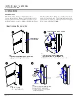
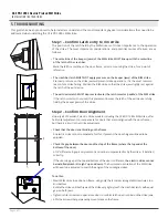
1. Using center line, measure 4
3
16
'' top and
bottom, and drill
Ø
5
8
''
hole for connecting wires, as per drawing.
2. Close door (Ensure crash bar latch does not touch keeper
while closing the door) if necessary, adjust strike so that strike
and crash bar latch are well aligned,
4. While adjusting strike, allow a small gap between strike body
and crash bar (approx.
1
8
''). Mark remaining screws position.
5. Open door and Remove strike. Drill threads at screws
position.
INSTALLATION INSTRUCTIONS
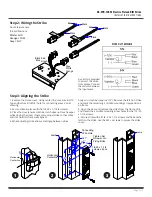
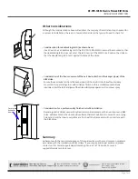
6. Connect wires as per drawing.
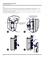
7. Fix strike with remaining screws
(1/4-20 x 1
1
2
(4pcs) at both ends / 10-32 x 1 and Remove latch
for (2pcs) in the middle
8. Door Status Sensor(Closed position)
White = NO
Orange = COM
Grey = NC
POWER
:
Red/Black,Blue/Green( 12VDC )
Red,Black/Blue,Green( 24VDC )
> Red / Green ( Short Black,Blue )
9. A varistor is provided to prevent strike from
spike.Connect varistor to between input wires.
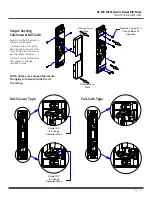
10. How to modify fail-Secure to fail-safe or vice versa.
(1) Remove the cover plate. Remove the 6 screws at the Front of
the Electric strike as per the diagram below.
(2) Rotate status mechanism 180 degree to change operation
mode
Red
Green
Black
Blue
12V
24V
Black
Red
Blue
Green
(+12V)
(-)
Varistor
(+24V)
(-)
Varistor
Jamb
Jamb
Orange
White
Grey
Black Red
12V
24V
R
Horizontal
Centerline
Fail-Secure Type
Fail-Safe Type
Rotate 180° to
Change
Operation Mode
Rotate 180° to
Change
Operation Mode
Remove 6 screws
To Change Mode
Of Operation
R+1''
Closed Door
Jamb
Top View
Latch
Allow a small gap between
strike body and crash bar
(Approx. 1/8'')
Crash Bar
Remove Cover
Plate
Remove Cover
Plate
R + 34
''
M3 x 6
(4pcs)
Closed
Door
Door Jamb
Crash Bar
Ensure latch does not touch
strike keeper while closing door,
and while adjusting strike
1
OPERATION MODE CHANGE
2
4
5
7
6
Latch
Monitor
Blue Green
3
2
1
2
''
Ø58
''
Horizontal
Centerline
Jamb
Jamb
Connecting
Wire hole
1. Using center line, measure 4
3
16
'' top and
bottom, and drill
Ø
5
8
''
hole for connecting wires, as per drawing.
2. Close door (Ensure crash bar latch does not touch keeper
while closing the door) if necessary, adjust strike so that strike
and crash bar latch are well aligned,
4. While adjusting strike, allow a small gap between strike body
and crash bar (approx.
1
8
''). Mark remaining screws position.
5. Open door and Remove strike. Drill threads at screws
position.
INSTALLATION INSTRUCTIONS
6. Connect wires as per drawing.
7. Fix strike with remaining screws
(1/4-20 x 1
1
2
(4pcs) at both ends / 10-32 x 1 and Remove latch
for (2pcs) in the middle
8. Door Status Sensor(Closed position)
White = NO
Orange = COM
Grey = NC
POWER
:
Red/Black,Blue/Green( 12VDC )
Red,Black/Blue,Green( 24VDC )
> Red / Green ( Short Black,Blue )
9. A varistor is provided to prevent strike from
spike.Connect varistor to between input wires.
10. How to modify fail-Secure to fail-safe or vice versa.
(1) Remove the cover plate. Remove the 6 screws at the Front of
the Electric strike as per the diagram below.
(2) Rotate status mechanism 180 degree to change operation
mode
Red
Green
Black
Blue
12V
24V
Black
Red
Blue
Green
(+12V)
(-)
Varistor
(+24V)
(-)
Varistor
Jamb
Jamb
Orange
White
Grey
Black Red
12V
24V
R
Horizontal
Centerline
Fail-Secure Type
Fail-Safe Type
Rotate 180° to
Change
Operation Mode
Rotate 180° to
Change
Operation Mode
Remove 6 screws
To Change Mode
Of Operation
R+1''
Closed Door
Jamb
Top View
Latch
Allow a small gap between
strike body and crash bar
(Approx. 1/8'')
Crash Bar
Remove Cover
Plate
Remove Cover
Plate
R + 34
''
M3 x 6
(4pcs)
Closed
Door
Door Jamb
Crash Bar
Ensure latch does not touch
strike keeper while closing door,
and while adjusting strike
1
OPERATION MODE CHANGE
2
4
5
7
6
Latch
Monitor
Blue Green
3
4
6
5
7


