background image

CX-EPD-1289L Electric Preload RIM Strike

INSTALLATION INSTRUCTIONS

Page 2 of 7

Introduction 

RIM electric strikes, used with Pullman latch devices 

(i.e. exit devices) are very different from installing an electric 

strike for cylindrical or mortise locksets, and therefore require 

additional considerations and a different installation technique.

Camden CX-EPD-1289L is designed to provide up to 15 lbs of 

preload on the strike keepers. This unique feature eliminates 

typical installation challenges caused by warped or misaligned 

doors, frames or locking hardware.

4. INSTALLATION

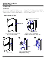
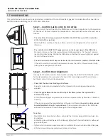
Step 1: Using the Install Jig

Align template edge

with the jamb edge 

Note:

1. Open door slightly. Place template on door jamb

    aligning templates edge with jamb edge.

Note:

1. Open door slightly, 

    and remove the template.

Note:

1. Close door making sure template is in place.

    Align Crash bar latch with template latch hole.

2. Mark holes center on the frame with a pencil or marker

Note:

1. Use a hole punch on marked positions.

2. Use drill size 5/8” to drill hole B

3. Drill pilot holes on A for self-tapping 

    screw (screw Ø 3/16) 

Template Edge in line with door jamb edge

Marker/

Pencil

Closed

Door

Door Jamb

Crash

Bar

Marker/

Pencil

Jamb

Jamb


Hole punch 

Hole punch 

Ø

5

8

''

Ø

5

8

''

3

8

''

43

16

''

43

16

''

158''

Connecting

wire hole

Connecting

wire hole

Holes for

self-tapping

screws

A

A

B

1

2

5

4

3

Summary of Contents for CX-EPD-1289L

Page 1: ...Fail Secure Only 15lbs Endurance 1 000 000 Cycles Factory Tested 250 000 Cycles UL Verified Latch Projection 3 4 Fire Rating UL 10C CAN4 S104 3 hrs Fail Secure Only Mode Field Selectable Fail Safe Fa...

Page 2: ...TION Step 1 Using the Install Jig Align template edge with the jamb edge Note 1 Open door slightly Place template on door jamb aligning templates edge with jamb edge Note 1 Open door slightly and remo...

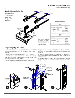
Page 3: ...Orange COM Grey N C 24V Black Blue Green Red 12V Black Black Black Red Black Red Grey White Orange Jamb 1 Remove the strike cover Using center line measure 43 16 top and bottom drill 5 8 hole for con...

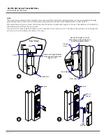
Page 4: ...POWER Red Black Blue Green 12VDC Red Black Blue Green 24VDC Red Green Short Black Blue 9 s 1 th m Jamb R 1 View Allow a small gap between strike body and crash bar Approx 1 8 Crash Bar Remove Cover P...

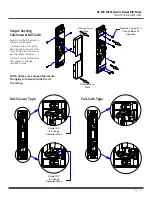
Page 5: ...fe type Fail Secure Type Fail Safe Type Step 4 Setting Fail Secure Fail Safe How to modify fail secure to fail safe or vice versa 1 Remove the cover plate Remove the 6 screws at the front of the elect...

Page 6: ...common reason for a strike failing Position the RIM strike so that the strike jaws lightly rest against the latch of the exit device Check that the door is not binding on the frame An electric strike...

Page 7: ...locking latch as shown here If exit device has a deadlocking latch the CX EPD 1289L RIM strike must be mounted so that the deadlocking latch does not enter the latch cavity of the RIM strike Position...

Reviews: