Camco V8 User Manual Download Page 14

VORTEX

S I LV E R   SE R I ES
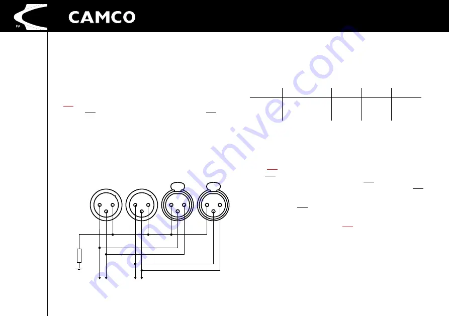
TO CHANNEL B

TO CHANNEL A

2

3

1

2

3

1

1

3

2

1

3

2

LINK B

LINK A

INPUT 

CHANNEL B

INPUT 

CHANNEL A

TO CHASSIS/EARTH

15 

Ω

USER MANUAL

VORTEX SILVER SERIES V8

P.13

3.4 Signal inputs

The 

V8

 amplifier offers three different input signal sources:

Analog

In this mode the analog signals connected to the XLR input connectors will 
be used as input signal. In analog mode the 

V8 

has 

no

 signal latency (with 

DSP switched off), the audio signal path is pure analog.

AES

In this mode the digital AES input signal connected to the AES XLR input 
connector will be used as input signal. 

Uman

With the Uman setting the input signals are taken from the Uman Digital 
Audio Network Interface.

3.4.1 Analog Input

XLR: 

Pin 1 = Ground (lifted via 15 Ω resistor to chassis / earth) 


Pin 2 = Hot (in-phase, "+") 


Pin 3 = Cold (out of phase, "−")

We suggest to always use symmetrically (balanced) shielded cable to con-
nect the amplifier.

The 

V8

 amplifier has a 26 dB and 32 dB voltage gain setting along with a 

1,4 V sensitivity setting.

The table shows input sensitivity per channel for a given gain and load. It 
also shows the gain for the 1,4 V input sensitivity. 

Model

rated output power

26 dB

32 dB

1,4 V

V8

5100 W @ 2 Ω
4000 W @ 4 Ω
2300 W @ 8 Ω

5,08 V
6,38 V
6,80 V

2,54 V
3,19 V
3,40 V

40 dB

3.4.2 AES Input

The digital AES XLR input accepts any AES/EBU signals (pro or consumer 
format) in 16, 18, 20 or 24 bit resolution and from 32 to 192 kHz samplig 
frequency. This wide input frequency range of is guaranteed by an inte-
grated sample rate converter (SRC) chip.

3.4.3 Uman  Input / Output

The Uman input and output connectors allow you to receive and send 
multichannel digital audio streams to other Uman-compatible devices 
(like other 

V8

 amplifiers for example). Please note that altough the Uman 

connectors use the same connector type than standard Ethernet (RJ-45), 
the physical transmission protocols are different. So any direct connec-
tion between the Uman connectors and standard Ethernet connectors 
will not work.

3.5 Remote control inputs (Ethernet / Uman)

The Ethernet Link network connector allows you to access the 

V8

 from 

a host computer for remote control, firmware update and downloading 
DSP presets. Please note that for setting up proper network connection 
we suggest to use the 

CAMCO

 NetSetup-Tool. This tool automatically 

sets up the needed network settings on your host computer for seamless 
communication.

If you want to connect more amplifiers (to one amplifier already con-
nected through the Ethernet Link) you can do so by connecting them to 

3 INST

ALLA

TION

Summary of Contents for V8

Page 1: ......

Page 2: ...il to the exclusion of the national translation on hand Copyright 2010 2012 by CAMCO Produktions und Vertriebs GmbH f r Beschallungs und Beleuchtungsanlagen Fischpicke 5 57482 Wenden Germany Telephone...

Page 3: ...ous injury and serious damage to the prod uct Any mounting of the amplifier should follow the manufacturer s instructions Only mounting accessory shall be used which is recommended by the manufac ture...

Page 4: ...a distinct change from its normal function or performance in case the amplifier has been used in a dusty environment for quite a period of time 13 Servicing All service and repair work must be carried...

Page 5: ...THE USER TO DANGEROUSLY HIGH VOLTAGE AT THE OUTPUT CONNECTORS THAT COULD POTENTIALLY BE LIFE THREATENING THE LIGHTNING FLASH WITH ARROW HEAD SYMBOL IS INTENDED TO ALERT THE USER TO THE PRESENCE OF UNI...

Page 6: ...Germany Declares That The Product With The Model Name CAMCO Power amplifier VORTEX SILVER SERIES V8 Conforms To The Following Standards EN60065 Safety EN55103 1 Emission EN55103 2 Immunity The operat...

Page 7: ...2 Power On Off P 18 4 3 Indicators 4 3 1 Input Selection LED 4 3 2 Output Mode LED 4 3 3 Clip LED 4 3 4 Signal LED 4 3 5 Device Identifier LED 4 3 6 DSP LED 4 3 7 Uman LED P 19 4 4 Main Menu 4 5 Power...

Page 8: ...elopers are able to take the next steps in building a more coherent future with tools that really integrate together The ancient cultures developed an understanding of our world by a reali sation of t...

Page 9: ...PS with automatic voltage range selection for 120 V 230 V operation which significantly reduces the weight and size only 2U of the amplifier Using SMPS the seamlessly regulated symmetrical supply volt...

Page 10: ...ion LED 10 DSP LED 4 Output Mode LED 11 Uman Network Status LED 5 Clip LED Channel A 12 Cooling Air Inlet Vents 6 Signal LED Channel A 13 Removable Air Filter System 7 Device Indicator LED 2 4 V8 The...

Page 11: ...ions to restore the original factory settings 1 The reset Settings option will restore all amplifier parameters and a reboot of the amplifier will take place Note that this type of reset is also done...

Page 12: ...ker for 120 V operation respectively Please do NOT use much larger mains breakers than recommended here and especially do NOT connect several V8 amplifiers to one sin gle very large breaker Always res...

Page 13: ...very high when demanding large output powers Please refer to following table for an overview of mains currents and power cunsuption under differ ent operating conditions Operating condition Mains cur...

Page 14: ...dB 1 4 V V8 5100 W 2 4000 W 4 2300 W 8 5 08 V 6 38 V 6 80 V 2 54 V 3 19 V 3 40 V 40 dB 3 4 2 AES Input The digital AES XLR input accepts any AES EBU signals pro or consumer format in 16 18 20 or 24 b...

Page 15: ...nnel B ground Pin 2 Channel A amplifier output Pin 2 Channel A ground WARNING SPEAKON connectors marked with the lightning flashes indicate high voltages that are potentially life threatening Wiringto...

Page 16: ...th SPEAKON connectors where possible for current sharing Not doing so may cause permanent damage to the connectors and may consid erably reduce performance 3 6 4 Mono Bridge Operation One channel mono...

Page 17: ...e to the selected menu item activate selected items confirm changes Shortcut key touch and hold 2 s to access the Quick Access Menu 3 A button Select channel A related parameters 4 B button Select cha...

Page 18: ...Hot Key accessible from all menus and screens Touch and hold MENU 2 s let you directly jump to the Home Menu You can step back to the previous screen by touching the MENU button The Home Menu can be...

Page 19: ...LED is illuminated when the input signal level is suffi ciently high for creating an output voltage of approx 4 V this corresponds to an output power of approx 4 W over a 4 load Note that these LED s...

Page 20: ...end ent approach The Clip Limiter works on each channel independently except for the two mono operation modes The Clip Limiter has three different modes Off Slow and Fast which can be selected in the...

Page 21: ...tput voltage These limits will be set automatically This improves reliability without de grading sound quality when driving complex loads 4 6 Mains Protections 4 6 1 Inrush Current Limitation Within 2...

Page 22: ...demanding for a mains distribution even with this limiter set to low values See also chapter 3 3 3 If active this limitation is indicated in the display s Signal Monitor and also by a red LED behind...

Page 23: ...is working If the amplifier has been powered down standby this LED will be slowly pulsating indicating that the SMPS is off but ready to be switched on again at any time Note that the picture shows th...

Page 24: ...lter no tools are required first gently slide the whole plastic filter assembly a few millimeters to the left and lift it from the front panel Next beginning on one of the long sides carefully unclip...

Page 25: ...operation typical values may be subjected to component tolerances Mono Bridge 4600 W 16 8000 W 8 10200 W 4 5000 W 16 Peak 9800 W 8 Peak 10600 W 4 Peak Parallel Mono 4600 W 4 8000 W 2 10200 W 1 5000 W...

Page 26: ...ower on off transients temperature monitoring of transformers and heatsinks output DC protection temperature dependent SOA protection intelligent mains fuse protection SMPS overload protection overcur...

Page 27: ...ormance will decrease with lower mains voltages than the rated 230 V 120 V and slightly increase with higher mains voltages Dual voltage SMPS with automatic voltage range selection 230 V 120 V 50 60 H...

Page 28: ...60 55 50 45 d B 60 10 50 40 30 20 10 0 dBu USER MANUAL VORTEX SILVER SERIES V8 P 27 Figure 6 1 Gain vs frequency 120 W output power 4 channel 1 channel 2 Measurement of a typical performance Figure 6...

Page 29: ...10 k Hz USER MANUAL VORTEX SILVER SERIES V8 P 28 Figure 6 6 Channel separation vs frequency 250 W 2 channel 1 channel 2 Measurement of a typical performance Figure 6 8 Common mode rejection ratio chan...

Page 30: ...THD Peak Power 0 1000 2000 3000 4000 5000 6000 Watts Impedance 5300 5100 4900 2500 1250 4000 2300 1250 USER MANUAL VORTEX SILVER SERIES V8 P 29 Figure 6 9 SMPTE intermodulation distortion 60 Hz and 7...

Page 31: ...ect AC voltage operation with faulty peripheral equipment modification or alteration without prior factory ap proval service by an unauthorized service center and normal wear and tear Amplifiers on wh...

Page 32: ..._ _ _ _ _ _ _ _ _ _ _ _ _ _ _ _ _ _ _ _ _ _ _ _ _ _ _ _ _ _ _ _ _ _ _ _ _ _ _ _ _ _ _ _ _ _ _ _ _ _ _ _ _ _ _ _ _ _ _ _ _ _ _ _ _ _ _ _ _ _ _ _ _ _ _ _ _ _ _ _ _ _ _ _ _ _ _ _ _ _ _ _ _ _ _ _ _ _ _ _...

Page 33: ...position to judge the safe functioning of power amplifiers based on technical rules according to IEC 60065 IEC 60065 DIN EN 60065 Safety Requirements for Audio Video or simlar Electronic Appliances I...

Page 34: ...3 Mailing Address CAMCO Produktions und Vertriebs GmbH f r Beschallungs und Beleuchtungsanlagen Fischpicke 5 57482 Wenden Germany Telephone 49 0 2762408 0 Facsimile 49 0 2762408 10 Internet www camcoa...

Page 35: ..._ _ _ _ _ _ _ _ _ _ _ _ _ _ _ _ _ _ _ _ _ _ _ _ _ _ _ _ _ _ _ _ _ _ _ _ _ _ _ _ _ _ _ _ _ _ _ _ _ _ _ _ _ _ _ _ _ _ _ _ _ _ _ _ _ _ _ _ _ _ _ _ _ _ _ _ _ _ _ _ _ _ _ _ _ _ _ _ _ _ _ _ _ _ _ _ _ _ _ _...

Page 36: ...www camcoaudio com...

Reviews: