Operation
212
Note
If the alignment is initiated from a CN, ensure that the operating channel is set on the
radio (before alignment). If the channel is not set, you must set the required channel
in the Configuration page of the V3000 single node UI.
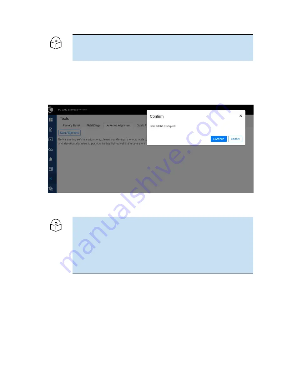
2. Click the Start Alignment button located at the top left side of the Antenna Alignment page.
The Confirm message box appears (as shown in
), indicating that the link will be
disrupted. For running the antenna alignment tool, the auto ignition needs to be disabled. If a link
has been established already, it is disassociated at this level.
Figure 231:
The Confirm message box in the Antenna Alignment page
3. In the Confirm message box, click Continue to start the antenna alignment process.
The antenna alignment process begins.
Note
If the alignment is initiated from a device (which is not running with Onboard
Controller), perform the following actions:
a. Disable the ignition of the link at the Controller.
b. Send Dis-assoc for the link from the Controller.
c. When the alignment starts, select the required node from the Remote Node
Model drop-down list.
The Time Frame section populates the RSSI time series as shown in
.
Summary of Contents for cnWave
Page 1: ...USER GUIDE 60 GHz cnWave System Release 1 2 2 ...
Page 56: ...System Hardware 56 Figure 37 10 GbE PoE C000000L141A ...
Page 136: ...Installation 136 Figure 128 Connecting the power injector to ODU drop cable ...
Page 205: ...Operation 205 SNR graph Figure 219 SNR graph MCS Index graph Figure 220 MCS Index graph ...


