Configuring 60 GHz cnWave™
184
1. From the home page of the device UI, navigate to the Configuration > Nodes > Networking page.
The Networking page appears.
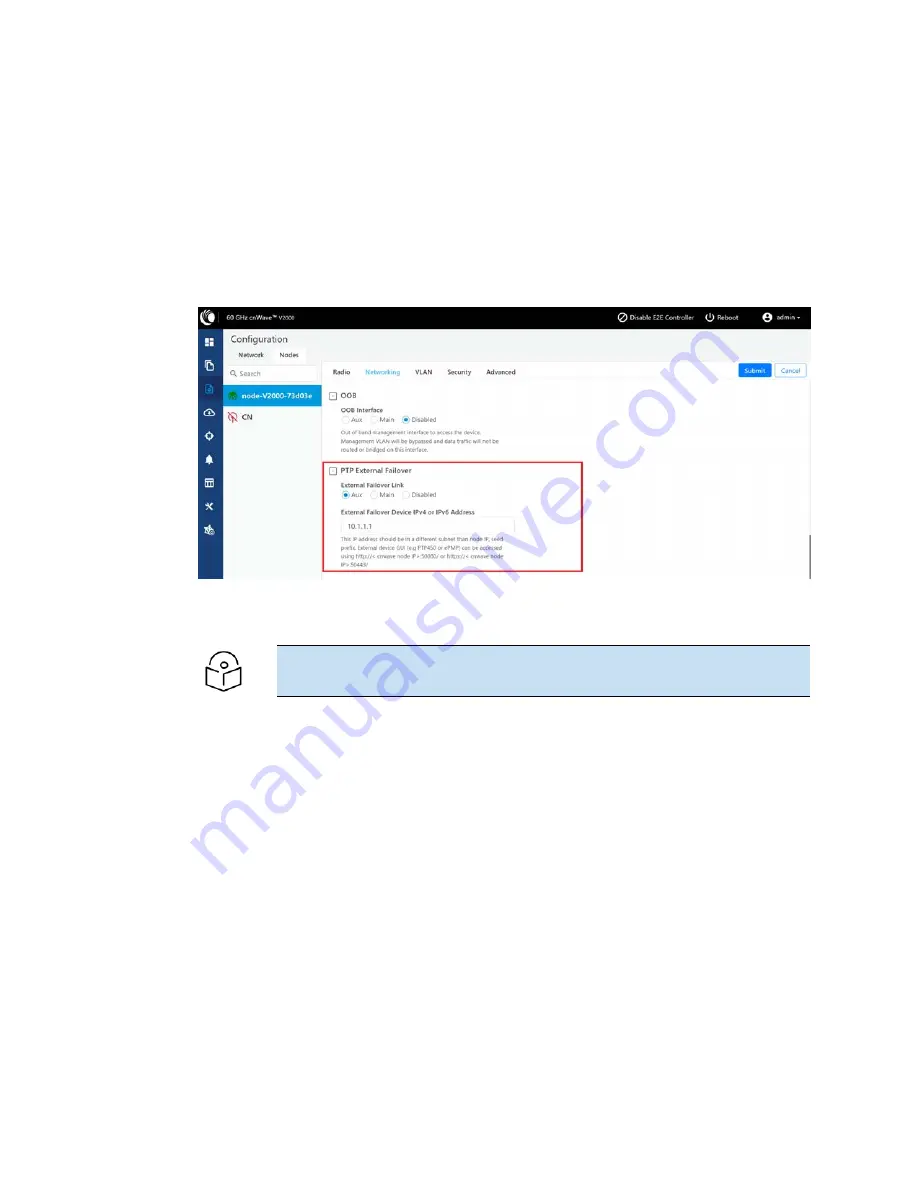
2. In the PTP External Failover section (as shown in
), set the following configurations:
a. To set the Ethernet interface for a node connected to external failover link, select either Aux
or Main (Ethernet ports) from the External Failover Link parameter.
By default, the Disabled option is selected.
Figure 190:
The PTP External Failover section in the device UI
b. Enter either IPv4 or IPv6 address of the external failover device In the External Failover
Device IPv4 or IPv6 Address text box.
Note
Ensure that IPv6 is enabled in the external failover device.
3. Click Submit to save the changes.
Using the cnMaestro UI
To configure the external failover link feature, add and manage the following configurations in the
Advanced page of cnMaestro UI:
l
Ethernet interface for each node: Configure the Ethernet interface in PoP and CN, which are
connected to the failover link. You must select the Ethernet port to which the external device is
connected. Open/R protocol runs on this interface.
l
External failover interface address (IP address): An optional configuration that is required only if
you want to access the AP or SM UI from the upstream. You must configure the IP address of
external devices (for example, PTP450 or ePMP). This IP address must be in a different subnet
other than node IP address or seed prefix.
The IP address can be either IPv4 or IPv6. However, ensure that external failover devices have IPv6
enabled.
Summary of Contents for cnWave
Page 1: ...USER GUIDE 60 GHz cnWave System Release 1 2 2 ...
Page 56: ...System Hardware 56 Figure 37 10 GbE PoE C000000L141A ...
Page 136: ...Installation 136 Figure 128 Connecting the power injector to ODU drop cable ...
Page 205: ...Operation 205 SNR graph Figure 219 SNR graph MCS Index graph Figure 220 MCS Index graph ...


