CalreC
Putting Sound in the Picture
21
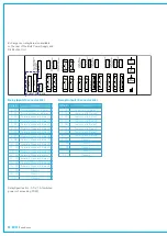
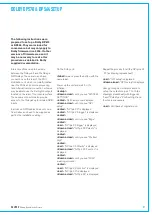
prOCessIng raCk
S
C
S
I
-
3
6
F
J120
A
D
C
3
#
1
-8
S
C
S
I
-
3
6
F
J121
A
D
C
3
#
9
-1
6
S
C
S
I
-
3
6
F
J101
A
D
C
2
#
1
-8
S
C
S
I
-
3
6
F
J103
A
D
C
2
#
9
-1
6
S
C
S
I
-
3
6
F
J95
A
D
C
1
#
1
-8
S
C
S
I
-
3
6
F
J96
A
D
C
1
#
9
-1
6
S
C
S
I
-
3
6
F
S
C
S
I
-
3
6
F
J122
J111
A
D
C
2
#
1
7
-2
4
A
D
C
3
#
1
7
-2
4
S
C
S
I
-
3
6
F
J97
A
D
C
1
#
1
7
-2
4
S
C
S
I
-
3
6
F
J127
A
D
C
3
#
2
5
-3
2
S
C
S
I
-
3
6
F
J115
A
D
C
2
#
2
5
-3
2
S
C
S
I
-
3
6
F
J104
A
D
C
1
#
2
5
-3
2
P
O
W
E
R
8
D
V
S
C
S
I -
3
6
F
J87
D
A
C
3
#
1
-1
6
S
C
S
I -
3
6
F
J82
D
A
C
2
#
1
-1
6
S
C
S
I -
3
6
F
J66
D
A
C
1
#
1
-1
6
S
C
S
I
-
3
6
F
J74
A
E
S
4
-I
N
#
1
-1
6
S
C
S
I -
3
6
F
J88
D
A
C
3
#
1
7
-3
2
S
C
S
I -
3
6
F
J83
D
A
C
2
#
1
7
-3
2
S
C
S
I -
3
6
F
J68
D
A
C
1
#
1
7
-3
2
S
C
S
I
-
3
6
F
J75
A
E
S
4
-O
U
T
#
1
-1
6
S
C
S
I
-
3
6
F
J57
A
E
S
3
-I
N
#
1
-1
6
S
C
S
I
-
3
6
F
J58
A
E
S
3
-O
U
T
#
1
-1
6
S
C
S
I
-
3
6
F
J47
A
E
S
2
-I
N
#
1
-1
6
S
C
S
I
-
3
6
F
J48
A
E
S
2
-O
U
T
#
1
-1
6
S
C
S
I
-
3
6
F
J62
A
E
S
1
-I
N
#
1
-1
6
S
C
S
I
-
3
6
F
J63
A
E
S
1
-O
U
T
#
1
-1
6
S
C
S
I
-
3
6
F
S
C
S
I
-
3
6
F
J67
J49
A
E
S
2
-I
N
#
1
7
-3
2
A
E
S
3
-I
N
#
1
7
-3
2
S
C
S
I
-
3
6
F
J41
A
E
S
1
-I
N
#
1
7
-3
2
S
C
S
I
-
3
6
F
J69
A
E
S
3
-O
U
T
#
1
7
-3
2
S
C
S
I
-
3
6
F
J51
A
E
S
2
-O
U
T
#
1
7
-3
2
S
C
S
I
-
3
6
F
J42
A
E
S
1
-O
U
T
#
1
7
-3
2
S
C
S
I
-
3
6
F
J76
A
E
S
4
-I
N
#
1
7
-3
2
S
C
S
I
-
3
6
F
J77
A
E
S
4
-O
U
T
#
1
7
-3
2
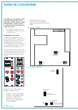
9M D-TYPE
DEBUG 2
J113
9M D-TYPE
DEBUG 1
J108
RJ45-8V
FAST LINK
J112
9F D-TYPE
POWER 5DV
J100
CH
J99
L2
BNX
005-01
L1
BNX
005-01
J102
TTL SYNC I/P
H121
H122
METER DATA
VIDEO SYNC I/P
J109
RJ45-8V
BNC
75
BNC
75
DC DIST
FAIL BOX
HN5638 PROCESSING RACK BACKPLANE
J32
J106
0L
J55
CH
J107
CR
Rear Interface
The 7U Processing rack houses the
system’s DSP, input, output and con-
trol cards. Incorporated into the rack
is a built-in low noise fan tray, situated
above the processing area. The fan
tray incorporates a baffle such that
warm air is drawn out of the rack and
out through the rear of the fan tray.
2 slots for DSP Cards
2 slots for Processor Cards
3 slots for ADC (Analog Input) Cards
3 slots for DAC (Analog Output)
Cards
4 slots for AES I/O cards, 3 of which
can house Wide Area Bulk Cards
Mounting
The unit should always be mounted in
a horizontal position, located into an
equipment bay and secured into the front
of the bay by the four fixing holes in each
of the two front angles.
•
•
•
•
•
Synchronization
The system can be pre-set with up to
five external sync sources, plus internal,
such that if the 1st source fails, it will
automatically switch to the 2nd, and so on.
It is strongly recommended that all items
of digital equipment connected digitally to
the console, are synchronized to the same
sync signal.
If the console’s internal sync is to be the
master, other digital equipment should be
synchronized to the digital outputs of the
console.
Please note that the facility for locking to
external AES sources is restricted to the
first six inputs of each AES card in the
console. One of the external sources can
be Video, (PAL or NTSC). TTL Word clock
is another possible external source.
Video and TTL Word clock
Synchronization
Connections for Video (PAL or NTSC) and
TTL Word Clock synchronization inputs
are provided on the rear of the Processing
rack, on 75
Ω
BNC connectors.
Frequency Variation
When using a digital input or word clock
as a source, the system will tolerate
a variation of up to +/- 100 Hz in the
frequency of the source. The console may
also be synchronized from its internal
crystal oscillator (48 kHz).
Summary of Contents for OMEGA
Page 7: ...calrec com OMEGA Putting Sound in the Picture Overview...
Page 13: ...calrec com OMEGA Putting Sound in the Picture Frame Options and Dimensions...
Page 18: ...18 OMEGA with Bluefin...
Page 19: ...calrec com OMEGA Putting Sound in the Picture Equipment Installation...
Page 37: ...calrec com OMEGA Putting Sound in the Picture Hydra Audio Networking...
Page 51: ...calrec com OMEGA Putting Sound in the Picture Audio I O Interfaces...


