background image

11

1002594 ISSUE 1 M172 VARIHEAT

It is essential to control the pool hall conditions 24 hours per day and, once 
commissioned, your Variheat should never be turned off if you are to avoid 
discomfort and/or expensive building damage due to humidity. It is a common 
mistake to believe that by turning the Variheat off will save running costs. This 
is not true. Turning the Variheat off turns off all the energy recovery it provides, 
and your swimming pool will cost you more to operate overall.

The energy usage and environment in a swimming pool are a delicate balance 
and your Variheat has been selected to operate at very specific conditions. The 
most important principle in a swimming pool is the difference between the air 
and water temperatures. For both economy and comfort, it is good practice 
to keep the air temperature in the pool hall 1-2°C above the pool water 
temperature while the cover is removed (Occupied Mode). A normal humidity 
target in a pool hall is 60%RH. These settings should correspond to the original 
design parameters for the project. Unless other conditions were specifically 
requested at the time the system was designed, the most common conditions 
used in indoor pools are:

— 

Water temperature 28°C-30°C

— 

Air temperature 29°C-30°C

— 

Relative Humidity 60%RH

Changing the settings may result in high power consumption or less effective 
control of the environment. If you:

— 

Increase the water temperature – evaporation from the swimming pool 
water will increase, running costs will increase, and the likelihood of 
condensation will increase.

— 

Reduce the water temperature – evaporation from the swimming pool 
water will reduce, running costs will reduce.

— 

Increase the air temperature – evaporation from the swimming pool water 
will reduce, running costs usually reduce. 

— 

Reduce the air temperature – evaporation from the swimming pool water 
will increase, running costs will increase, and the likelihood of discomfort 
and condensation will increase.

— 

Increase the humidity – running costs will reduce, but comfort will worsen, 
and the likelihood of condensation will increase.

— 

Reduce the humidity – running costs will increase, but may not improve 
comfort, nor reduce the likelihood of condensation. 

If you do find it necessary to adjust settings, firstly ensure that the control 
system sensors are measuring accurately by using a calibrated thermometer 
and always maintain the air 1°C higher than water temperature. The settings for 
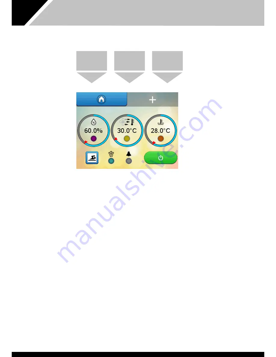
humidity, air temperature and pool temperature can be changed by touching 
the centre of the corresponding parameter. A keypad appears. (See page 10.)

Unless the Variheat has been specifically chosen for the purpose, do 
not operate with the air temperature below the water temperature 
when the cover is removed.

The only exception is when a floating cover is in place on the pool (Unoccupied 
Mode). 

HUMIDITY AND TEMPERATURE SETTINGS

POOL HALL 

HUMIDITY 

(%RH)

POOL HALL AIR 

TEMPERATURE 

(°C)

POOL WATER 

TEMPERATURE 

(°C)

Summary of Contents for Variheat AW1200

Page 1: ...1 1002594 ISSUE 1 M172 VARIHEAT Variheat system AW600 900 1200 1500 Owner installation manual 1002594 issue 1...

Page 2: ......

Page 3: ...ARIHEAT TOUCHSCREEN 31 3 0 INSTALLATION 33 3 1 SITING MACHINE LOCATION 34 3 3 FRESH AIR AND EXHAUST AIR 36 3 4 PLUMBING INSTALLATION 37 3 5 ELECTROLYTIC CORROSION IN SWIMMING POOLS 41 3 6 ELECTRICAL C...

Page 4: ...or instruction concerning the use of the appliance in a safe way and understand the hazards involved Children should not play with the appliance Cleaning and maintenance shall not be made by children...

Page 5: ...d humidity from the swimming pool hall and provide swimming pool water heating Heat recovery from the heat pump is usually sufficient to supply the majority of the evaporation heat losses from the mai...

Page 6: ...re any servicing or electrical work commences When unlit power is disconnected but remote interfaces connected to the Variheat from other systems may still be live Ethernet port for connection to a lo...

Page 7: ...a white background can be modified except where locked by the User Security settings Grey buttons and parameters with a grey background cannot be modified See page 21 Pressing the button shows the sec...

Page 8: ...temperature setting Key to lights Yellow solid air heating via LPHW operating Blue solid free cooling operating if optional fresh air module is fitted 3 Pool water temperature C Number shows current...

Page 9: ...19 Standby switch Green and white ON Variheat is powered and operating according to the control system settings Red and white user Standby Variheat is powered but not operating The Variheat has been...

Page 10: ...o Unoccupied mode If remote control of Occupied Unoccupied is to be used this control should be set to Unoccupied See page 12 7 User settings Allows the user to change the settings of the Variheat use...

Page 11: ...of the environment If you Increase the water temperature evaporation from the swimming pool water will increase running costs will increase and the likelihood of condensation will increase Reduce the...

Page 12: ...riod settings User override button Remote system connected to the interface terminals In Occupied Mode all functions operate according to User Settings In Unoccupied Mode the following functions chang...

Page 13: ...keypad appears for number entry an alphabet appears for text entry The keypad for entering numeric parameters is shown below The parameter to be modified is shown at the top The allowable range that...

Page 14: ...the cog button on the second Home screen Controller Clock Occupied Unoccupied periods Alarms Set Points and Switches Dance Hall Mode Language User Security Data Monitoring USER SETTINGS INSERT THE PI...

Page 15: ...s isolated from power or if there is an interruption to the power supply which lasts longer than three days DAYLIGHT SAVING TIME This button is red when daylight saving is disabled and green when dayl...

Page 16: ...e Occupied period is required period B can be disabled The current Occupied air temperature and the Unoccupied air temperature settings are shown The Unoccupied setting is set as the difference betwee...

Page 17: ...menu The Alarms screen displays warnings or faults with the Variheat indicated by a red highlight The example above indicates that there is a problem with the pool water flow rate that should be inves...

Page 18: ...ings Home icon Return to Home screen This screen duplicates settings on the Home screens If functions on the Home screens are disabled by the User Security settings they may be accessed here Note the...

Page 19: ...Hall Mode until disabled by the user Dance Hall Mode is not intended to be used for a long period If Dance Hall Mode is enabled for a long time the pool water temperature may fall outside the normal...

Page 20: ...ALLATION MANUAL LANGUAGE Press this button on the Settings menu Arrow icon Return to User Settings Home icon Return to Home screen The available languages are shown on this screen and can be selected...

Page 21: ...er Settings Home icon Return to Home screen Password Disabled Password Disabled When Security Mode is enabled the buttons shown on the screen can be toggled between grey and orange Settings in grey ca...

Page 22: ...password screen The factory default Webgate password is DefaultPass For security reasons Calorex recommends that this password is changed If the password is changed write it in the box below and keep...

Page 23: ...brings up a graph of the selected parameter Choose from Air temperature Humidity Water temperature and Alarms The display is marked up in hours and shows the past 72 hours of activity HUMIDITY LOG WA...

Page 24: ...n the future Offsets Screen Settings Customer Timers IP Address BMS Settings Reset to Factory settings Advanced Settings Press this button on the Settings menu WARNING ACCESSING THE ADVANCED SETTINGS...

Page 25: ...y For example the Variheat displays a pool temperature of 27 5 C and a calibrated thermometer measures 28 0 C In this instance an offset of 0 5 C can be applied to calibrate the sensor The single arro...

Page 26: ...ress Home to return to the Home screen The Reset Standby Switch on Power Loss button determines what happens when power is interrupted When set to ON the Variheat restarts in Standby mode when power i...

Page 27: ...esponse as follows factory defaults Occupied mode no delay Unoccupied mode 1 hour The delay timers can be edited from this screen The sum of the Occupied and Unoccupied timers cannot be more than 23 h...

Page 28: ...rn to the Advanced Setting screen or if nothing else needs to be changed press Home to return to the Home screen FACTORY RESET Press this button on the Advanced Settings menu Arrow icon Return to User...

Page 29: ...Used Can be set from 2 to 4 corresponding to 2 uNET 3 Modbus RTU 4 BACnet MS TP Data Bit Always set to 8 Included for information only to configure own software if needed Parity Bit Can be set from 0...

Page 30: ...g Modbus RTU or BACnet MS TP see the BMS Settings screen on page 31 Enable DHCP This button toggles between DHCP enabled or disabled IP Address Subnet Mask Default Gateway Primary and Secondary DNS al...

Page 31: ...jeo Design Air app must be installed on the device A free version is available with a limited connection time A paid version is available with unlimited access After installing the app open it and sel...

Page 32: ...e Variheat can be controlled with a mouse as if using the integral touchscreen Numbers and text can be entered with a keyboard ActiveX browser first time set up procedure Follow the user access instru...

Page 33: ...e separated to assist positioning where plantroom access is restricted The following actions need to be completed Disconnect flexible LPHW hoses Disconnect fan wiring taking care to record all wire po...

Page 34: ...lter and all Service panel Service panel Alternative supply air position Horizontal range Service panel if not ducted Air fillter access panel Service panel Removable cover gives acces to electric box...

Page 35: ...ol hall Horizontal range Service panel Damper Service panel Air filter access panel Spigot Service panel Electric box assembly Supply air to pool hall Removable display panel gives access to electric...

Page 36: ...is less than 7m then a full height separator panel may be required to prevent recirculation Exhaust air out Fresh air in Return air from pool hall Notes 1 Ensure duct work pressure drop including all...

Page 37: ...ipe should run away with adequate fall to waste ie per foot min and must incorporate a U trap and tun dish LPHW plumbing The LPHW connections for connecting the boiler water flow and return to the Var...

Page 38: ...d which would normally be the case with a well managed system then no problems should be encountered Setting up the differential When installation is complete the procedure for setting the flow rate t...

Page 39: ...flow meter Isolating valve A Bypass valve Locking gate valve type AUX heater if fitted Fig 3 Pump Pool Filter Bypass valve C Locking gate valve type Non return valve or loop Aux heater if fitted Isol...

Page 40: ...AW1200 1500 BOILER WATER OUT BSPM AW600 900 1 BSPM ON AW1200 1500 POOL WATER IN 1 BSPM POOL WATER OUT 1 BSPM DRAIN BSPM AIR FILTER ACCESS PANEL SERVICE PANEL MAINS IN 25mm DIA MACHINE WITH STANDARD F...

Page 41: ...al electrolyte and components of the filtration circuit heating system steps lights etc providing the dissimilar metals needed to complete the circuit Whilst these small voltages are rarely a safety t...

Page 42: ...location to the alternative position if this is more convenient for the user to access With the power isolated and the black cover removed the screen rear can be removed by pressing the button on top...

Page 43: ...440V Frequency 47 5Hz 52 5Hz Note The voltage must be measured at the heat pump mains terminals with all the fans compressors running at the rated load condition Correct cable sizing The cable supply...

Page 44: ...MANUAL EARTH STUD 1 3 5 6 4 2 2 1 E L1 MCB 3 5 4 6 L2L3 Customer terminations to heater box See notes in section 3 8 Separate mains supply terminal blocks for resistance heater boxes layout single and...

Page 45: ...f Link if not used Main Fan Fault Link if not used Common Fuse 800mA Machine On Fault Total maximum load 500mA Soft Start Interlock 6 7 8 9 Boiler Go Pool pump Terminals 1 20 Terminals 49 76 Earth Ear...

Page 46: ...be used Pool Pump Run demand terminals 8 9 See page 47 Time clock override remote Occupied Unoccupied control terminals 10 11 For remote control of the Variheat Occupied Unoccupied mode To enable Occu...

Page 47: ...th the pool pump time clock the pool filtration pump will run when a A pump on period has been set by the time clock for filtration purposes b The Variheat needs to provide heat recovery to the pool w...

Page 48: ...n is deactivated If the temperature is still too cold the machine remains in Advanced Frost Protection mode until the next check An option to force a check can be found on the Set Points and Switches...

Page 49: ...IP BACnet MS TP Modbus is available via the RS485 2 interface on the PLC BACnet IP is available via the Ethernet port on the PLC BACnet MS TP is available via the RS485 2 interface on the PLC Only on...

Page 50: ...easurement of the conditions When using 0 5mm cable the maximum total distance between the sensors and their terminals is 20 metres After the Remote Sensor Box has been connected it may be necessary t...

Page 51: ...ery to air priority to help heat the pool hall see User Settings Commissioning For full commissioning procedure please refer to separate commissioning document and report which should be completed ful...

Page 52: ...tenance requirements See 4 1 4 1 MAINTENANCE Operations carried out during a planned maintenance visit are as follows 1 Replace all belts filters where fitted 2 Check operation and condition of all fa...

Page 53: ...SANYO PANASONIC COMPRESSOR ONLY C S R 27 28 10V Vsp GND RES HEATER CONTROL IF FITTED FAN MOTOR L N 5 7 6 TO FIRE ALARM RELAY R2 9 6 45 46 0 10V INPUT 10V Vsp GND FRESH AIR BOX FAN L N EARTH N COMPRESS...

Page 54: ...54 1002594 ISSUE 1 M172 VARIHEAT VARIHEAT AW SYSTEM OWNER INSTALLATION MANUAL BLUE BLUE WHITE BROWN RELAY 3 FUSE 91 800mA CAP OFF UNUSED CABLES HMI SCREEN FUSE 92 160mA 21 22 COMPRESSOR CONTACTOR...

Page 55: ...55 1002594 ISSUE 1 M172 VARIHEAT...

Page 56: ...3 61 7 4 9 48 0 3 2 6 Electrical data Typical high pressure system with constant flow fan Typical low pressure system with constant flow fan Minimum supply capacity FLA 230V 1N 50Hz Minimum supply ca...

Page 57: ...50 55 60 65 70 75 80 t u p t u o d e t a r f o LPHW flow temperature C Air heater performance correction Standard LPHW Standard LPHW 0 20 40 60 80 100 120 140 45 50 55 60 65 70 75 80 t u p t u o d e...

Page 58: ...f 182 115 108 75 100 130 Supply air to pool hall 2184 355 Fresh air box Service panel Damper Resistance heaters If fitted In this position only 670 Spigots See above 190 60 160 1339 Air filter access...

Page 59: ...BSPM Pool water in 1 BSPM Pool water out 1 BSPM Drain BSPM Air filter access panel Service panel Variheat with fresh air negative pressure box and or resistance heater module Resistance heater if fitt...

Page 60: ...r positions 349 Alternative supply air position Fresh air box Service panel 670 2024 355 160 Air filter access panel Service panel Variheat with fresh air negative pressure box and or resistance heate...

Page 61: ...tion only Service panel Electric box assembly Service panel Supply air to pool hall Variheat without optional modules Service panel Service panel Air filter access panel Alternative supply air positio...

Page 62: ...71 729 800 Cabinet 71 222 355 784 1558 Cabinet 33 33 Floor duct spigot supplied Floor duct spigot supplied 149 Cabinet foot Cabinet foot Cabinet foot Floor duct spigot supplied Cabinet foot Cabinet fo...

Page 63: ...0 1558 945 182 140 135 125 75 Mains in through dianeter 25mm 2off Electric box assembly 1460 1105 Boiler water in 1 BSPM Boiler water out 1 BSPM Pool water in 1 BSPM Pool water out 1 BSPM Drain BSPM A...

Page 64: ...nce heater if filled n this position only Service panel 2503 LPHW in 1 BSPM LPHW out 1 BSPM Pool water in 1 BSPM Pool water out 1 BSPM Drain BSPM 289 Service panel Service panel 772 Air filter access...

Page 65: ...160 60 182 140 135 125 75 LPHW in 1 BSPM LPHW out 1 BSPM Pool water in 1 BSPM Pool water out 1 BSPM Drain BSPM Air filter access panel Service panel Variheat with fresh air negative prseeure box and o...

Page 66: ...ir box Service panel Air filter access panel Service panel Variheat with fresh air negative pressure box and or resistance heater module Resistance heater if fitted in this position only Service panel...

Page 67: ...urn air Return air Return air Return air Return air Return air Return air Return air Return air Supply air to pool hall Supply air Supply air Supply air Supply air Supply air Supply air Supply air Sup...

Page 68: ...ir Supply air Electric box Return air Supply air Electric box Return air Supply air Electric box Return air Supply air Return air Supply air Electric box Electric box Return air Supply air Electric bo...

Page 69: ...ir from pool hall Return air Return air Return air Electric box Return air Return air Return air Return air Return air Return air Return air Return air Return air Supply air to pool hall Supply air Su...

Page 70: ...ined in accordance with service requirements in section 4 1 If in doubt or if advice is required please contact the Calorex Service Department by calling 01621 857171 or emailing service calorex com N...

Page 71: ...71 1002594 ISSUE 1 M172 VARIHEAT...

Page 72: ...72 1002594 ISSUE 1 M172 VARIHEAT Calorex Heat Pumps Limited The Causeway Maldon Essex CM9 4XD United Kingdom t 44 0 1621 856611 e sales calorex com www calorex com...

Reviews: