


37
Proprietary Information: Not for use or disclosure except by written agreement with Calix.
© Calix. All Rights Reserved.
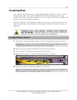
Wiring the External Alarm and Timing Interfaces
This section describes how to wire external alarms and external (BITS) timing interfaces to
the Calix E7-2. The E7-2 terminates its alarm and timing interfaces via wire-wrap pins
located on the E7-2 rear panel.
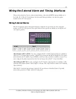
Wiring External Alarms
The E7-2 supports eight external alarm input/output (I/O) positions via wire wrap pins
located on the E7-2 rear panel. The eight external alarm positions include seven inputs and
one output position.
Output
Input
OUT+
AL1+
AL2+
AL3+
AL4+
AL5+
AL6+
AL7+
OUT-
AL1-
AL2-
AL3-
AL4-
AL5-
AL6-
AL7-
Alarm Inputs (AL1 to AL7):
You can configure the E7-2 alarm input positions to interface
with up to (7) external input sources, typically for environmental alarm conditions. The input
alarm contacts are Normally Open (default), and close when an alarm condition occurs. You
can configure the alarm type and severity for each input from the E7-2 user interfaces.
Alarm Output (OUT):
You can configure the E7-2 alarm output position to interface with
external office alarm systems such as lights or horns. The output alarm contacts are Normally
Open (default).
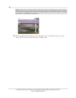
Wire the E7-2 external alarm input/output (I/O) positions as described below. Typically,
alarm wiring consists of black and white wire pairs.
Summary of Contents for E7-2
Page 1: ...Calix E7 2 Installation Guide May 2013 220 00320 Rev 13...
Page 2: ......


