Manufactured in the U.S.A.
alum
LEDs
™
CALIFORNIA ACCENT LIGHTING, INC.
2820 E. Gretta Lane, Anaheim, CA 92806
ph. 800.921.CALI (2254) | fx. 714.535.7902 | [email protected] | calilighting.com
© CALI. All rights reserved. CALI reserves the right to make changes or withdraw specifications without prior notice.
Page 10 of 11
INSTALLATION
ALS
600T-AD
2019.12.5 Rev 2
Troubleshooting & Continuity Test
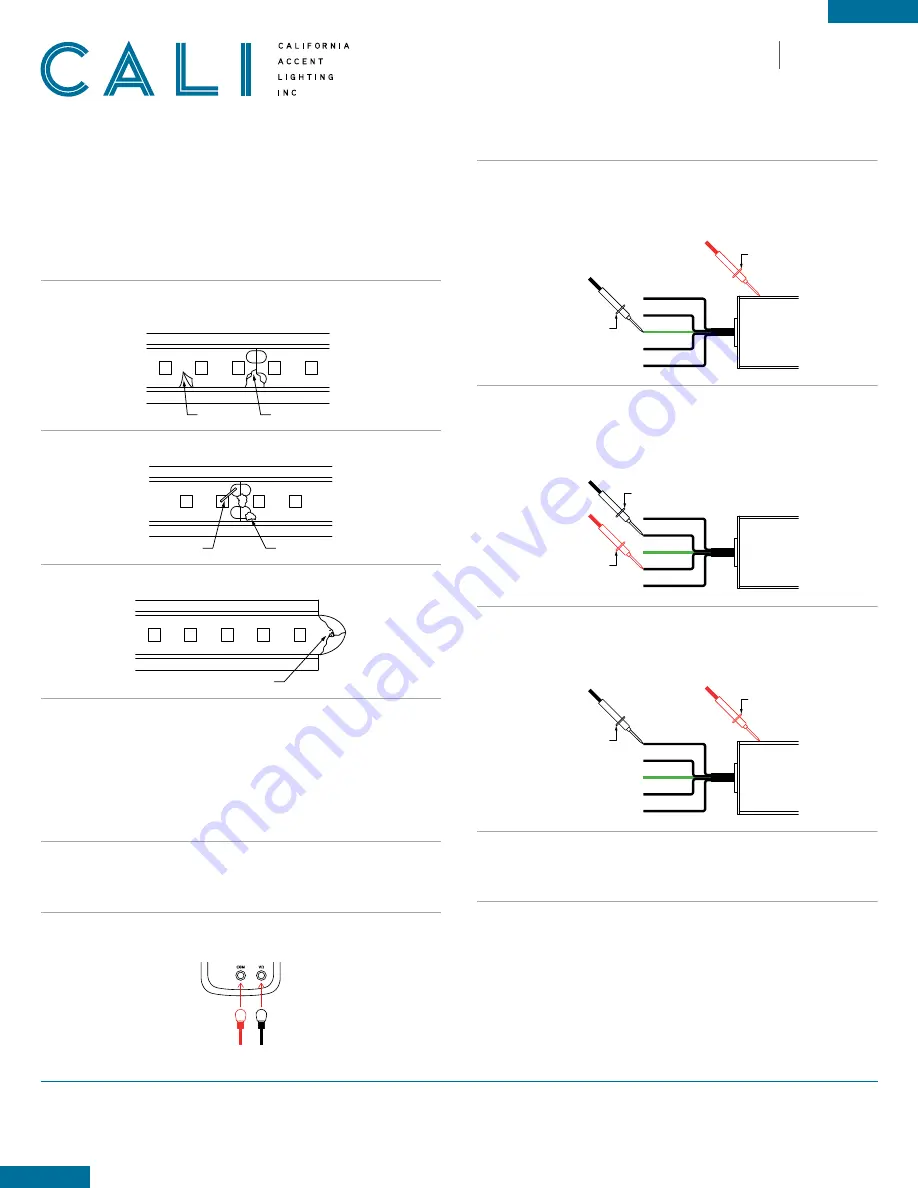
Frayed end
Copper pads touching extrusion
Foreign object
Lightstrip overlapping extrusion
Metal flakes
Damaged lightstrip
Twisted lightstrip
Torn lightstrip
Frayed end
Copper pads touching extrusion
Foreign object
Lightstrip overlapping extrusion
Metal flakes
Damaged lightstrip
Twisted lightstrip
Torn lightstrip
Frayed end
Copper pads touching extrusion
Foreign object
Lightstrip overlapping extrusion
Metal flakes
Damaged lightstrip
Twisted lightstrip
Torn lightstrip
1.
Turn off power before beginning. Check for any twisting or damage to the circuit in the LED
lightstrip. If there is excessive damage and the circuit is broken, the lightstrip must be replaced.
3.
Check to ensure lightstrip is clean and not frayed, causing copper pads to touch.
2.
Check for metal particles or other foreign objects causing the short.
TROUBLESHOOTING TIPS
• Do not reset the breaker multiple times
• If the unit is overloaded, the breaker will trip, shutting off the transformer and lights
• If the breaker reset button has been held down by hand or any type of pressure, such as duct
tape, or if the breaker has been reset multiple times without troubleshooting, the unit will:
- Burn the transformer bobbin
- Burn the thermal or magnetic breaker
- Burn the primary or secondary wires due to high amperage caused by overload
- Short circuit in line which will not allow the breaker to reset
- Damage the lighting
1.
Turn power off before beginning. Verify power is turned off by using a non-contact circuit
tester. Touch the probe of the tester to positive wire of the power source. The tester will
light up if an electrical current is detected.
3.
Verify that your tester is functional by touching probes together. The tester should light up,
beep, or read 0Ω (ohms) of resistance.
5.
Touch the red probe to a wire and the black probe to each other wire. Repeat for each wire.
If a conductive path is formed between any of the wires, the multimeter will beep, flash,
or read
0Ω
(ohms). Troubleshoot to identify the malfunction in the line. If there is no
conductive path, the multimeter will not show any feedback.
Example:
Check for continuity between Wire 2 and Wire 4
6.
Touch the red probe to the fixture extrusion and the black probe to each wire except ground.
If a conductive path is formed between the extrusion and any of the wires, the multimeter
will beep, flash, or read
0Ω
(ohms). Troubleshoot to identify the malfunction in the line.
If there is no conductive path, the multimeter will not show any feedback.
4.
Touch the red probe to the fixture extrusion and the black probe to the ground wire (green).
If the fixture is properly grounded, the multimeter will beep, flash, or read
0Ω
(ohms).
If there is no conductive path, the multimeter will not show any feedback. Troubleshoot to
identify the malfunction in the ground wire.
7.
Set voltmeter to AC voltage and test power source. Confirm the correct voltage before
connecting lighting to power source. If voltage reading is more than 1 volt higher than the
marked output voltage, there is a problem with the power source or driver.
8.
Connect power connector to power source. If LEDs do not turn on, troubleshoot to find the
problem in the line.
CONTINUITY TEST
A continuity test is performed to determine if electricity can pass through two points on
an electrical circuit. This helps identify shorts or malfunctions in the line or fixture. Use a
multimeter or continuity tester to perform the steps below.
• Always perform a continuity test before connecting lighting to power source.
• Malfunctions are not always as obvious as the lights not turning on.
• A short or malfunction in the line or fixture will cause damage over time, ultimately damaging
the lighting and voiding warranty.
2.
Setup your tester. First insert the black probe lead into the COM jack, then insert the red
probe lead into the VΩ jack.
1
2
V
AC
(-)
(+)
Black Probe
Red Probe
1
2
3
4
5
Red Probe
Black Probe
1
2
3
4
5
Red Probe
Black Probe
1
2
3
4
5
Red Probe
Black Probe
1
2
3
4
5
Red Probe
Black Probe
1
2
3
4
5
Red Probe
Black Probe
1
2
3
4
5
Red Probe
Black Probe
1
2
3
4
5
Red Probe
Black Probe
1
2
3
4
5
Red Probe
Black Probe
1
2
3
4
5
Red Probe
Black Probe


