CALI alumLEDs ALS500T-RMW-TB Installation Instructions Manual Download Page 4

CALIFORNIA ACCENT LIGHTING, INC.

2820 E. Gretta Lane, Anaheim, CA 92806
ph. 800.921.CALI (2254) | fx. 714.535.7902 | [email protected] | calilighting.com

© CALI. All rights reserved. CALI reserves the right to make changes or withdraw specifications without prior notice.

1 / 29 / 2021 / Rev 2

Page 4 of 16

ALS

500T-RMW-TB

INSTALLATION INSTRUCTIONS

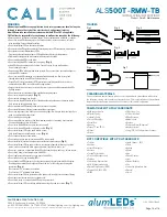
Mounting (Hanging Bracket Assembly ) 1 of 2

Countersink Screw

Rail Bracket

Hex Nut

8-32 x 2”

Hex Head Bolt

Lock Washer

Slot

Hanging Bracket Arm

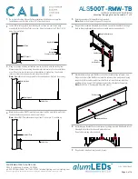
Do not install ceiling tiles until after installation of luminaires is complete. 
Installation area must have at least 10” of overhead space.

1

Determine number of Hanging Brackets required.

Note:

 Refer to the diagrams on page 10 as a guide.     

5

If applicable, assemble Hanging Bracket Arms. Insert Hex Head Bolts through 
slots on Hanging Bracket Arms and secure with washers and hex nuts. 

6

Mark locations where each Rail Bracket will be installed along reference line. 
Align the bottom of the Rail Bracket with the reference line and pre-drill using 
proper drill bit for surface and screw size. Each rail must be mounted with a 
minimum of two screws. Drill additional holes in Rail Brackets if necessary. 

Note:

 Use 8/32 x 2” Countersink Screw (By others)

7

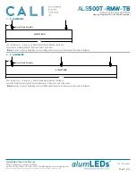
If applicable, install end caps to ends of runs.
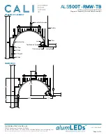
9

Install T-Bar ceiling grid. Assemble the grid so there is a continuous edge 
around grid for the Ceiling Trim to rest on. Hang the center of the T-Bar 7-5/16” 
away from wall stud.

2

Hang or cut drywall along installation area so it is flush with the ceiling line. 
Measure exactly 4” above ceiling line and mark each wall stud in the installation 
area. Use a laser level to ensure accurate relation to ceiling line, then draw a 
reference line connecting each mark along the wall studs.

Note:

 Drywallers must hang drywall to the specifications. Only cut if necessary.
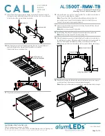
3

Mark locations along Wall Trim extrusion where it will be mounted to wall studs, 
then drill holes as needed and mount to wall studs. 

Note:

 Mount Wall Trim extrusion using at least 1 screw per 2’, rounded up.

4

7-5/16”

5/8” Drywall

T-Bar

Support Wire

Wall Stud

Maintain

Continuous Edge

Ceiling Line

Mark Wall Stud

4”

Top of drywall

Mount Wall Trim

Ceiling Line

Install Hanging Bracket Arms to luminaire by sliding inverted Hex Head Bolts of 
Hanging Bracket into the channels pictured below.
Do not slide into any other channels.

8

Summary of Contents for alumLEDs ALS500T-RMW-TB

Page 1: ...d 24VDC Output Voltage To calculate driver size determine Watts per Foot Example 4W per Foot Determine Length in Feet Example 20 To calculate Load Multiply Watts per Foot x Length in Feet Example 4W x...

Page 2: ...Power Source To Power Source Circuit 2H White Circuit 1H Gray KEY A Standard Length Luminaire runs are constructed in 8 segments B Custom Length Any required length that is not 8 Typically the last se...

Page 3: ...rior notice 1 29 2021 Rev 2 Page 3 of 16 ALS500T RMW TB INSTALLATION INSTRUCTIONS Diagram of Assembly Hanging Bracket Assembly Hex Screw Channel Tie Wire Tie Wire Wall Stud Rail Bracket Lock Washer Co...

Page 4: ...be mounted with a minimum of two screws Drill additional holes in Rail Brackets if necessary Note Use 8 32 x 2 Countersink Screw By others 7 If applicable install end caps to ends of runs 9 Install T...

Page 5: ...screws by others Do not mount drivers between luminaires Note Driver size and location of mounting holes may differ from below example 15 Make wiring connections from driver to 1st PCB Pull lead wires...

Page 6: ...t to make changes or withdraw specifications without prior notice 1 29 2021 Rev 2 Page 6 of 16 ALS500T RMW TB INSTALLATION INSTRUCTIONS Diagram of Assembly Aircraft Cable Assembly 5 8 Drywall 1 8 Mud...

Page 7: ...a continuous edge around grid for the Ceiling Trim to rest on Hang the center of the T Bar 7 5 16 away from wall stud 2 Hang or cut drywall along installation area so it is flush with ceiling line Not...

Page 8: ...run 11 All aircraft cables must rest in a vertical position Do not allow aircraft cables to rest at a slant or angle Adjust as needed Note The position of the Aircraft Cable Assemblies may deviate fro...

Page 9: ...from driver Verify wiring diagram before connecting 17 Perform a continuity test before connecting luminaire to power source Refer to page 15 for continuity test step by step 18 Verify driver wire col...

Page 10: ...et Rail Bracket ALS500T RMW 6 8 Hanging Bracket Rail Bracket For luminaires 1 long use 1 Rail Bracket and 2 Hanging Brackets Install 2 Hanging Brackets 2 from each end of 1 Rail Bracket Align the 1 Ra...

Page 11: ...1 5 Aircraft Cable Assembly 4 ALS500T RMW 6 8 Aircraft Cable Assembly 4 For luminaires 1 5 long use 2 Aircraft Cable Assemblies per luminaire Install each assembly about 4 from each end of luminaire N...

Page 12: ...le Block to meet the Female Block Tighten Allen Screws using provided Allen Wrench to close the gap until luminaires meet Only tighten screws until extrusion edges meet with no gaps Over tightening sc...

Page 13: ...between trim and fixtures not aligned Install Trim Retention Springs to ceiling trim Use one clip per 2 or two clips per segment under 4 Install clips 4 from each edge evenly spaced 3 Measure and cut...

Page 14: ...URES MAINTENANCE SPECIFICATIONS REFLECTANCE 550NM 97 5 0 8 ASTM E1164 L VALUE 98 9 ASTM E308 A VALUE 0 35 0 25 ASTM E308 B VALUE 0 90 0 30 ASTM E308 GLOSS 60 5 0 ASTM D2456 THICKNESS 205 m 15 Ono Sokk...

Page 15: ...ath is formed between the positive and negative wires the multimeter will beep flash or read 0 ohms Troubleshoot to identify the malfunction in the line If there is no conductive path the multimeter w...

Page 16: ...ctory for any malfunctions Do not attempt to repair Only use alumLEDs with specified rated voltages Do not exceed the specified voltage for any alumLEDs luminaire Do not use alumLEDs extrusion as a ra...

Reviews: