


CALIFORNIA ACCENT LIGHTING, INC.
2820 E. Gretta Lane, Anaheim, CA 92806
ph. 800.921.CALI (2254) | fx. 714.535.7902 | [email protected] | calilighting.com
© CALI. All rights reserved. CALI reserves the right to make changes or withdraw specifications without prior notice.
1 / 29 / 2021 / Rev 2
Page 14 of 16
ALS
500T-RMW-TB
INSTALLATION INSTRUCTIONS
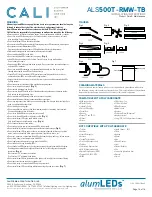
Installing Reflective Film (ALS500T-RMW-RF-98)
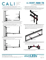
Second, insert edge of film
into wall-side gap between
the wall trim and extrusion.
First, insert edge of film into the
gap between lens and extrusion.
Do not cover lens with film.
Lens
Extrusion
Wall Trim
1
2
• Follow the below diagrams and steps if applicable to your installation.
• Only install Reflective Film after all other installation requirements are
complete. Lighting must be tested and in working order, and wall must be
mudded, painted, and completely dry before beginning.
• Reflective Film requires a minimum of two people to ensure a secure and
correct installation.
• Use a puller stand to prevent damage to the film while installing.
• Installers must wear gloves while handling Reflective Film.
• The Reflective Film is two-sided. Place the textured side facing downward.
The smooth side should only be facing upward.
INSTALLATION GUIDELINES
• Stable in humid environments
• Anti-static
• Abrasion resistant
• Continuous thermal stability up to 100°C
• Compatible with the following cleaning solutions: dilute ammonia, soap
solutions, Clorox Wipes, Pine-Sol, and Formula 409
FEATURES & MAINTENANCE
SPECIFICATIONS
REFLECTANCE @ 550
NM
97.5 ± 0.8% (ASTM E1164)
L* VALUE
> 98.9 (ASTM E308)
A VALUE
-0.35 ± 0.25 (ASTM E308)
B VALUE
0.90 ± 0.30 (ASTM E308)
GLOSS (60°)
< 5.0% (ASTM D2456)
THICKNESS
205 µm ± 15 (Ono Sokki EG225)
TENSILE STRENGTH
165 MPa (ASTM D882)
DEFORMATION TEMPERATURE
130°C (JIS K7196-1991)
MELT TEMPERATURE
255°C (ASTM D3418)
UL RELATIVE THERMAL INDEX
105°C (UL746)
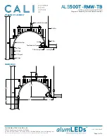
Installation Area
Reflective Film
Puller Stand
One person installs Reflective Film
according to the instructions below.
Another person feeds film from
puller stand to installer, ensuring
that film is not disturbed in the process.
Installers must wear gloves
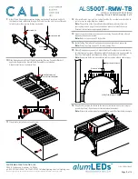
Miter Square
Reflective Film
Rough edge
Location of new cut
Clean edge
Cut a 1’ section of Reflective Film and practice installing to get a feeling for how
it bends and forms in the luminaire. The film cannot be corrected if it is bent,
folded, wrinkled, or kinked during installation.
1
Place roll of Reflective Film onto wire puller stand. Gently pull film from roll
and feed to installer as needed. Check that the textured side is facing downward
when pulling.
3
Place beginning edge all the way to the end, so the edge of the film sits flush to
the end cap.
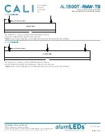
4
At the end of the run, estimate how much more film will be needed. Make small
cuts at the end of the film and test fit it. Repeat if necessary until the film meets
the end cap flush.
5
Check along entire run that Reflective Film is installed correctly. Ensure lens is
not covered by film and that it is securely tucked into each edge along the run.
6
If applicable, cut the end of the sheet so it has a smooth and even edge.
Tip:
Use a tool to ensure an accurate cut.
2


