CALEFFI SATK22107 Instructions For Installation, Commissioning And Maintenance Download Page 15

15

Δ

H (m w.g.)

G (m

3

/h)

p (bar)

3

0,6

0,4

0,3

0,2

0,1

0

2,5

2

1,5

0,5

0,5

3,5

3

1

6

4

3

2

1

5

7

0,7

0,8

8

Constant head

Proportional head

Constant speed

Factory setting

Factory setting

SATK20403

pump only

SATK20103

available 

head

Δ

H (m w.g.)

G (m

3

/h)

p (bar)

3

0,4

0,3

0,2

0,1

0

1,25

1,00

0,75

0,25

0,5

1,5

0,50

6

4

3

2

1

5

7

8

Factory setting

Δ

H (m w.g.)

G (m

3

/h)

p (bar)

3

0,4

0,3

0,2

0,1

0

1,25

1,00

0,75

0,25

0,5

1,5

0,50

6

4

3

2

1

5

7

8

SATK30103

available 

head

Constant head

Proportional head

Constant head

Proportional head

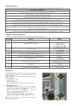
Circulator - Curves and setting

CARATTERISTICA PROPORZIONALE

CARATTERISTICA COSTANTE

GIRI FISSI

CURVA 1 (MIN)

CURVA 2

CURVA 3

CURVA 4 (MAX)

ALARM STATUS

Blocked
Supply voltage low 
Electrical error

LED SEQUENCE

CURVE TYPE

0

PROPORTIONAL AUTO ADAPT

1

CONSTANT AUTO ADAPT

2

PROPORTIONAL 1

3

PROPORTIONAL 2

4

PROPORTIONAL 3 - MAX

5

CONSTANT 1

6

CONSTANT 2

7

CONSTANT 3 - MAX

8

FIXED SPEED 1

9

FIXED SPEED 2

10

FIXED SPEED 3 - MAX

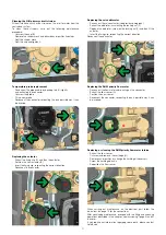
The HIU is equipped with a Grundfos circulator model UPM3 AUTO 

15-70.

By default, the circulator setting is with the maximum proportional 

head characteristic.

To change the characteristic, hold down the front key for more than

two seconds and then press the same key repeatedly until reaching

the required characteristic (refer to the figure below).

Having identified the required characteristic (head - flow rate chart 

shown below) wait for about ten seconds for the setting to be 

accepted by the circulator, which will then revert to the sequence of 

LEDs showing power consumption.

The pump also has a self-diagnostics system to reveal any possible 

operating problems.

Any problem 

detected is shown 

by a sequence of 

LEDs:

A long press of the front key (>10 s) locks the pump setting, preventing 

possible incorrect modifications of the curve. Unlocking can be done 

in the same way, with a long press (>10 s) of the front key.

CARATTERISTICA PROPORZIONALE

CARATTERISTICA COSTANTE

GIRI FISSI

CURVA 1 (MIN)

CURVA 2

CURVA 3

CURVA 4 (MAX)

ALARM STATUS

Blocked
Supply voltage low 
Electrical error

LED SEQUENCE

CURVE TYPE

0

PROPORTIONAL AUTO ADAPT

1

CONSTANT AUTO ADAPT

2

PROPORTIONAL 1

3

PROPORTIONAL 2

4

PROPORTIONAL 3 - MAX

5

CONSTANT 1

6

CONSTANT 2

7

CONSTANT 3 - MAX

8

FIXED SPEED 1

9

FIXED SPEED 2

10

FIXED SPEED 3 - MAX

Summary of Contents for SATK22107

Page 1: ...mestic hot water capacity 50 kW 1 With primary pump SATK22405 Direct wall mounted HIU for HIGH temp heating Domestic hot water capacity 60 kW 1 With primary pump SATK22407 Direct wall mounted HIU for...

Page 2: ...acteristics of both units into consideration 10 An combination coupling could compromise the operation of the device and or system IMPORTANT Risk of electric shock Live parts Shut off the electric sup...

Page 3: ...primary circuit Dp 600 kPa 6 bar Domestic water circuit max flow rate 24 l min 0 4 l s Minimum flow rate to activate domestic water flow meter 2 l min 0 3 Electric supply 230 V ac 10 50Hz Max power c...

Page 4: ...r primary circuit air vent Characteristic components SATK2210 LOW temperature Hydraulic diagram SATK2210 and SATK2220 TS TA 2 V V V V V V 3 4 7 12 13 5 6 8 9 10 11 21 14 15 19 24 20 17 16 17 22 23 25...

Page 5: ...draulic diagram SATK2230 and SATK2240 TS TA 2 V V V V V V 3 4 7 12 13 5 6 8 9 10 11 21 14 15 19 24 20 17 16 17 22 23 25 TA 2 V V V V V V 3 4 7 5 6 8 9 10 11 21 13 14 19 22 20 23 16 17 18 SATK2210 only...

Page 6: ...out template code 789023 Hydraulic installation Preliminary operations installation without template After having established the point of installation of the appliance perform the following operation...

Page 7: ...bottom Connections on the top Heat meter installation The HIU is fitted to house a compact heat meter with incorporated return probe with 1 threaded connections and length of 130 mm Before carrying o...

Page 8: ...directed toward the exterior of the HIU using the pathways provided in the insulation and on the frame All the low voltage lines must be routed through a single dedicated cable raceway using the path...

Page 9: ...ntrol Refer to the dedicated user manual for the procedure Filling the central heating system Open the shut off valves on the connections to the centralised line and in the central heating system proc...

Page 10: ...riarmabile funzione scaldamassetto R mode ACS ON OFF Risc ON OFF set Ora giorno corrente Temperature di set point k regolazione climatica day night Set diurno nottu prog Programmazione oraria riscalda...

Page 11: ...oint k regolazione climatica day night Set diurno notturno temp Visualizzazione temperature set point ambiente sonde prog Programmazione oraria riscaldamento e funzione comfort reset Reset errore riar...

Page 12: ...ed the display shows the symbol OPTIONAL SETTING weather compensation technical parameter t01 3 When the function is enabled the flow temperature is calculated based on the temperature detected by the...

Page 13: ...menu see access to technical menu below Parameter t07 1 freezes the operating set points to prevent inadvertent modifications by the user The comfort function can be alternatively preheating of the DH...

Page 14: ...ntrolling the maximum opening of the primary circuit modulating valve Since latter is controlled by a differential pressure limiter it is possible to supply direct correspondence between the opening p...

Page 15: ...wo seconds and then press the same key repeatedly until reaching the required characteristic refer to the figure below Having identified the required characteristic head flow rate chart shown below wa...

Page 16: ...xternal primary flow pump normally OFF The contact must be closed if any HIU function is active DHW production heating pre heating Parameter t05 must be set to 1 2 4 7 example 2 Distinction of consump...

Page 17: ...ire twisted cable Compliance with this requirement becomes even more significant the more extensive the RS 485 network If alternatively a shielded wire is used the shield must be connected solely on t...

Page 18: ...code 76 Corrective action Normal operating conditions are restored automatically once the faulty safety valve works properly again reriscaldo circolo Impostazione default limitazione portata massima...

Page 19: ...PAID AUX RS 4 IN IN IN OUT IN OUT EXP PORT OTS RT PREPAID AUX RS 485 BUS IN IN IN OUT IN OUT EXP PORT OTS RT PREPAID AUX RS 485 BUS IN IN IN OUT IN OUT EXP PORT OTS RT PREPAID AUX RS 485 BUS IN IN IN...

Page 20: ...pty the heat interface unit using the drain cocks provided Exchanger replacement As a preliminary step remove the flow sensor refer to replacing the DHW priority flow meter on page 21 and position it...

Page 21: ...e previous paragraph Extract the obturator unscrewing the locking nut F Replace the obturator screw on the locking nut F and then fit the actuator Insert the fixing clip respecting the correct directi...

Page 22: ...ature set point disable the function primary circuit strainer of the HIU clogged call qualified personnel to have it serviced exchanger partly clogged call qualified personnel to have it serviced modu...

Page 23: ...on in charge of system electronic regulator not working call qualified personnel to have it replaced primary circuit flow rate insufficient contact person in charge of system centralised system not wo...

Page 24: ...if required been carried out 13 Has the remote user interface been configured for installation on board thermostat function disabled inside the apartment with thermostat function enabled 14 Have the h...

Reviews: