background image


#9 Viper_SC_Manual_

001-5008-000_Rev12e.docx | 

Page 20


3


QUICKSTART 

It is easy to set up a Viper network to verify basic operation and to experiment with network designs and configurations. To 
eliminate unnecessary disruption of traffic on the existing network while you become familiar with Viper, you should use a 
network IP subnet address different from others currently in use in your test area.  

3.1


PC LAN SETUP 

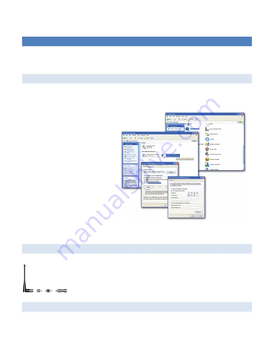
On a PC running MS-Windows with an existing LAN connection, connect to the Ethernet input of the Viper SC and complete 
the following steps. 

1)


From the PC, select 

Start

 → 

Settings

 → 

Control Panel

 → 

Network Connections


2)


Right-click 

Local Area Connection

 to 

open the Properties box. 
 

3)


From the list, select 

Internet Protocol 

(TCP/IP)

 and click 

Properties

 to open 

the TCP/IP Properties box.   
 

4)


Select 

Use the Following IP Address


and enter:  

a.


IP Address: 192.168.205.100 

b.


Subnet Mask: 255.255.255.0 

c.


Default Gateway: Leave empty 


5)


Click 

OK

 to apply your changes. Some 

Operating systems may require you to 
reboot your computer to complete this 
connection process. 


3.2


INSTALL THE ANTENNA 


An RX/TX antenna is required for basic operation. For demo units only, connect the 
antenna as shown to provide stable radio communications between demo devices.  

It is important to use attenuation between all demo units in the test network to reduce the 
amount of signal strength in the test environment.  

3.3


MEASURE AND CONNECT PRIMARY POWER 

Primary power for Viper must be within 10-30 VDC and be capable of providing a minimum of:  

Summary of Contents for Viper 100

Page 1: ...VIPER SC VIPER SC IP ROUTER FOR LICENSED SPECTRUM User Manual PN 001 5008 000 Rev 11 Revised August 2011...

Page 2: ...or Viper SC 200 Added information about V1 7 Viper SC firmware Release Corrected radio firmware upgrade command line instructions errors in Section 13 3 that were introduced in revision 7 of the user...

Page 3: ...Exposure Compliance Requirements The Viper SC radio is intended for use in the Industrial Monitoring and Control and SCADA markets The Viper SC unit must be professionally installed and must ensure a...

Page 4: ...generates uses and can radiate radio frequency energy and if not installed and used in accordance with the instruction manual may cause harmful interference to radio communications Operation of this...

Page 5: ...rt by Exception 11 2 1 4 Extending the Coverage Area with a Relay Point 11 2 2 IP Forwarding Modes 11 2 2 1 Bridge Mode 12 2 2 2 Router Mode 14 2 2 3 Multispeed Networking 16 2 3 System Planning 17 2...

Page 6: ...IP Addressing 55 4 4 4 IP Optimization 57 4 4 5 IP routing 59 4 4 6 Time Source 59 4 4 7 Alarm Reporting Diagnostic Settings 60 4 4 8 User Settings 61 4 5 SECURITY 62 4 5 1 Password and Encryption 62...

Page 7: ...eak RF Link 90 5 2 1 Use Router Mode with RF Acknowledgements Enabled 90 5 2 2 Reduce RF Network Bit Rate 90 5 2 3 Increase OIP and MAC Retries Limit 91 6 UPGRADING YOUR FIRMWARE 92 6 1 Upgrade Proced...

Page 8: ...MP IPinIP IPSec RSVP TCP and UDP protocols It provides MAC layer bridging and HTTP ARP and static routing packet forwarding 1 2 OPERATIONAL CHARACTERISTICS Viper has the following operational characte...

Page 9: ...s the dimensions of the chassis and mounting plate Figure 1 Chassis and Mounting Plate The equipment is intended for installation only in a RESTRICTED ACCESS LOCATION per EN60950 1 2006 1 3 2 LED PANE...

Page 10: ...0 BaseT Ethernet connection with Auto MDIX 1 50 ohm TNC female Antenna connector 1 50 ohm SMA female receive antenna connector Dual Port models only 1 Right angle power connector 10 30 VDC 2 DE 9F RS...

Page 11: ...ted to the Viper SC s serial ports is Data Terminal Equipment DTE and a straight through cable is recommended If a DCE device is connected to the Viper serial ports a null modem cable adapter is requi...

Page 12: ...n removed or the area is known to be non hazardous WARNING EXPLOSION HAZARD Substitution of components may impair suitability for Class I Division 2 The unit must be powered with a Listed Class 2 or L...

Page 13: ...0 512 MHz Viper SC 400 Range 5 140 5048 503 450 512 MHz Viper SC 400 Range 5 Dual Port 140 5048 600 450 512 MHz Viper SC 400 Range 5 AS NZ Compliant 250 5048 500 450 512 MHz Viper SC 400 Range 5 Demo...

Page 14: ...e 5 Redundant Base Station EN 300 113 Compliant AS NZ Compliant Table 6 Antenna Kits Part Number Frequency Description 250 0211 007 138 143 MHz 6 5 dB Antenna Kit 250 0211 010 138 143 MHz 9 5 dB Anten...

Page 15: ...jumper cable and weather kit UHF and 900 kits include 25 feet of LMR400 VHF kits require feedline be purchased separately LMR400 feedline is available in 25 and 50 feet Table 7 Accessories Model Numbe...

Page 16: ...er SCs will buffer reply messages because the dominant RTU radio is transmitting carrier is present A Viper SC will buffer while a carrier is present a reply message until it can capture the airwave c...

Page 17: ...tems The Master Polling station communicates with any number of remotes and controls the network by issuing polls and waiting for remote responses Individual PLC RTU remotes manage addressing and resp...

Page 18: ...NG THE COVERAGE AREA WITH A RELAY POINT A Viper can be configured as a Relay Point Relay Points provide store and forward repeating of necessary information from one coverage area to the next In Bridg...

Page 19: ...hat the subnet size is The first IP address in the subnet is the Network ID The last IP address in the subnet is the Broadcast Address Bridge Mode Example 1 Example one illustrates a sample Viper netw...

Page 20: ...rted to binary The first address 172 20 0 0 is reserved for the Network ID The last address 172 20 255 255 is reserved for the broadcast address There are 65534 valid IP addresses available to be assi...

Page 21: ...2 168 205 1 and a unique RF IP address This RF IP address will have the form 10 x y z where x y and z is based on the last 6 digits of the unit s Ethernet MAC address The default network is 10 0 0 0 8...

Page 22: ...24 RF IP Address 10 11 12 25 8 PLC 1 192 168 205 2 24 Computer HMI 1 192 168 205 3 24 Viper 2 Ethernet IP Address 192 168 206 1 24 RF IP Address 10 9 7 251 8 PLC 2 192 168 206 2 24 Viper 3 Eth IP Addr...

Page 23: ...ddress 10 0 0 177 16 Viper 178 Eth IP Address 10 200 12 17 28 RF IP Address 10 0 0 178 16 Figure 9 Router Mode Example 2 2 2 3 MULTISPEED NETWORKING When using Viper SC with a Viper SC 19 rack mount b...

Page 24: ...ul thought must be given to selecting the site for each radio Suitable sites should provide the following Protection from direct weather exposure A source of adequate and stable primary power Suitable...

Page 25: ...for most projects 2 3 3 RADIO INTERFERENCE Interference is possible in any radio system However since the Viper is designed for use in a licensed system interference is less likely because geographic...

Page 26: ...bright spot on the wall the light might be a thousand times greater than it would be without the reflector The resulting bulb reflector combination has a gain of 1000 or 30 dB compared to the bulb alo...

Page 27: ...on to open the Properties box 3 From the list select Internet Protocol TCP IP and click Properties to open the TCP IP Properties box 4 Select Use the Following IP Address and enter a IP Address 192 16...

Page 28: ...green 3 5 CONFIGURE YOUR VIPER Viper must be configured using the Setup Wizard This quick start will use the Setup Wizard to configure your Viper for bridge mode operation For other configuration opt...

Page 29: ...guide you through Viper configuration for operation Read the onscreen instructions carefully before proceeding Figure 11 Setup Wizard Welcome Quit to exit the Setup Wizard Next to proceed STEP 1 Figur...

Page 30: ...TEP 2 Each Viper SC is programmed with these defaults IP Address 192 168 205 1 Network Mask 255 255 255 0 Default Gateway 0 0 0 0 To monitor or change configuration remotely each unit requires a uniqu...

Page 31: ...acket Bit Rate Select desired bit rate in kbps RX Frequency Enter RX Frequency TX Frequency Enter TX Frequency TX Power Enter 5 0 W Click Apply Click Next STEP 4 Figure 15 Setup Wizard STEP 4 The Vipe...

Page 32: ...phrase is Dataradio Click Apply Click Next STEP 5 Figure 16 Setup Wizard STEP 5 Click Done Click Save Config to save the network parameters for your Viper SC You will see a green success icon on the b...

Page 33: ...ity see Section 4 5 Statistics see Section 4 6 Maintenance see Section 4 7 Network Management see Section 0 The navigation frame also contains the Save Config and Reset Unit command buttons Save Confi...

Page 34: ...rame select Unit Status to display General and Diagnostic data for the device 4 1 1 GENERAL The Identification and Status banner displays the software revision information Ex Vx y_Rxxx Vx y is revisio...

Page 35: ...On Self Test FAILURE Warning Radio TX Synthesizer lock failure N A use the ACKNOWLEGDE UNIT STATUS and REFRESH buttons to reset the modem If the problem persists contact CalAmp Technical Services for...

Page 36: ...ine will report normal The Viper SC radio can be configured to send an SNMP trap if the Reverse Power goes into a fault state Power State Reports Full normal Fault Indicates if the unit is running at...

Page 37: ...splays the IP Address of the destination Viper SC This is the destination station from the point of view of RSSI measurements A Temperature of the source Viper SC in Celsius or Fahrenheit Temperature...

Page 38: ...al to 0 4 2 SETUP WIZARD Refer to Section 3 5 2 Quick Start to use the Setup Wizard to configure your Viper 4 3 BASIC SETUP From the navigation frame select Basic Setup to configure General IP Channel...

Page 39: ...municate at a fixed data rate Refer to Appendix A for data rates by model Select Enabled to configure the Viper unit to be a rate follower This means the Viper will adjust its over the air data rate t...

Page 40: ...erver will be accessible to you If your network does not support DHCP server capability the unit will be reset to the default 192 168 205 1 IP address IP Address Default 192 168 205 1 Set a valid uniq...

Page 41: ...0 0 must be the same for all Viper in the network MTU Maximum Transfer Unit Enter a value from 576 1500 Default 1500 This value represents the maximum number of bytes Viper will send in a packet MAC...

Page 42: ...9 Viper_SC_Manual_001 5008 000_Rev12e docx Page 35 Figure 23 Setup Basic Channel Table...

Page 43: ...id frequency has been entered Viper will not transmit until valid RX and TX frequencies have been entered and this radio button has been deselected There are 32 channels available The radio button bes...

Page 44: ...9 Viper_SC_Manual_001 5008 000_Rev12e docx Page 37...

Page 45: ...lways Asserted Envelope Mode the DCD will be asserted only when data is present at the serial port Packet Forwarding Threshold Mark Character time allows the user to change time based on the character...

Page 46: ...hod of data transmission with acknowledgements and retries built into the protocol TCP requires several handshaking messages to open a connection close a connection and to acknowledge that a packet ha...

Page 47: ...st Broadcast or Multicast IP address REQUIRED Value Unicast IP address UNUSED Value N A REQUIRED Value Unicast IP address TCP Keepalive UNUSED OPTIONAL Value 0 1440 min 0 TCP Keepalive disabled OPTION...

Page 48: ...ved successfully by the remote endpoint the TCP connection will remain open If the keepalive message is not received successfully the Viper SC will close the existing TCP connection To disable this fe...

Page 49: ...non persistent carrier sensing to transmit a request to send RTS and the receiver sends a clear to send CTS RTS CTS handshaking protocol enables the Viper SC network to avoid collisions in networks w...

Page 50: ...Viper SC will try to receive and decode any and all messages from remote Viper SCs When data is ready to transmit Viper SC will first check the receive level If the receive level is below the carrier...

Page 51: ...9 Viper_SC_Manual_001 5008 000_Rev12e docx Page 44 4 4 2 IP SERVICES From the navigation frame select Setup Advanced IP Services to configure RIPV2 IPSD NAT and SNMP Figure 26 IP Services...

Page 52: ...SNMP is based on the manager agent model consisting of a manager an agent a database of management information managed objects and the network protocol The manager provides the interface between the h...

Page 53: ...messages Viper MIB Files Each Viper firmware package is bundled with three MIB files found inside mibs zip file 1 dataradio regs MIB contains a top level set of managed object definitions aimed at man...

Page 54: ...perate SNMP MIB For all Viper SC the same password is used for both read and read write This password is the same password used to access the Viper SC web pages Figure 29 shows top level objects of th...

Page 55: ...s in the masqueraded network since this establishes the translation tables For example a web browser in the masqueraded network can browse a website outside but a web browser outside could not browse...

Page 56: ...the private network The user can select which of two interfaces Ethernet or RF will be considered private The following examples illustrate how to configure the Viper SCs The examples use a private ne...

Page 57: ...ll not be able to ping or originate a message to Host 1 when NAT Eth enabled 4 4 2 2 1 2 RF INTERFACE PRIVATE Figure 34 shows the NAT enabled for the RF interface Figure 34 NAT Enabled RF Private Figu...

Page 58: ...s configuration the Ethernet IP address for Viper 1 is considered private and the RF IP address for Viper 2 is considered private Figure 36 shows how the packets will be modified as the packets pass t...

Page 59: ...ce does not originate from the private RF network 4 4 2 3 USER NAT ENTRIES The user can add three USER IP addresses that will be considered private Figure 39 shows USER1 192 168 205 125 and USER2 192...

Page 60: ...k hidden by the Network Address Translation Table The user can also select between TCP and UDP protocols Figure 40 shows the NAT Eth IP subnet 192 168 205 0 will be hidden from the Public Network Any...

Page 61: ...he Public Network 172 31 5 0 Viper 1 NAT Eth interface is enabled and Viper 2 NAT is disabled The Host 172 31 5 2 cannot send packets directly to the Private Network because it is hidden In this examp...

Page 62: ...0 14 203 2000 port 2000 Figure 42 shows how the packets would be modified as they moved through the network Figure 42 Packet Flow Port Redirection 4 4 3 IP ADDRESSING There are some SCADA PLC protocol...

Page 63: ...abled Forwarding of directed broadcast packets is enabled default Disabled Forwarding of directed broadcast packets is disabled Limited Broadcast This parameter controls the forwarding of limited broa...

Page 64: ...rsion of the destination IP address from multicast to broadcast is disabled default Multicast to Broadcast RF to LAN When a multicast packet is forwarded from the RF interface to the LAN interface the...

Page 65: ...er unless OIP Retries is set to 0 Other types of packets are only retried if RF ACK is enabled TCP Proxy The TCP proxy optimizes the throughput of a TCP connection by removing some of the TCP packets...

Page 66: ...rvice QoS Enables or disables the RF Quality of Service algorithm Enabled by default this algorithm classifies data according to the local physical interface by which it enters the Viper to ensure tha...

Page 67: ...e last update received from the SNTP Server in seconds Default 0 4 4 6 2 TIME ZONE Select Local Time Zone from list Default GMT Greenwich Mean Time Daylight Saving Select Enabled Disabled Default Disa...

Page 68: ...econd notification is sent indicating the error has cleared For example assume the Viper SC is programmed to transmit at 10W If the measured reverse power increases above 5 0W then the error is detect...

Page 69: ...d must be 8 15 characters in length 4 5 1 2 ENCRYPTION Viper uses Advanced Encryption Standard AES 128 encryption AES 128 is a block cipher adopted as an encryption standard by the government Encrypti...

Page 70: ...ho wish to connect to a unit through the Viper SC Web Interface the FTP server or the command shell RADIUS can also be used to authenticate devices based on their MAC addresses Unauthorized devices wi...

Page 71: ...l database RADIUS When accessing the HTTP server check the user credentials against the RADIUS server If the user credentials fail to match with the RADIUS server access to the HTTP server is denied I...

Page 72: ...N provides a secure connection between two points over an insecure network for example the Internet This secure connection is called a VPN Tunnel Viper units feature a firewall friendly proprietary VP...

Page 73: ...9 Viper_SC_Manual_001 5008 000_Rev12e docx Page 66 Figure 54 Viper VPN Network with Relay Point Figure 55 Security VPN Settings...

Page 74: ...aster Key that is 32 bytes 32 characters This Key Strength is the same for all VPN keys The Master Key Strength must be the same for the VPN server and all its clients Master Key Since hexadecimal num...

Page 75: ...number of active tunnels terminating in the unit The maximum number of key exchanging tunnels is currently limited to 128 on a VPN server and 1 on a VPN client A Shared tunnel is included in this stat...

Page 76: ...ed If enabled VPN service starts automatically when Viper is powered on 4 5 3 5 SERVER SETTINGS Block non VPN Traffic Select Enabled Disabled Default Enabled If enabled the VPN service blocks all pack...

Page 77: ...a value to configure the number of Idle Probes to attempt without receiving a reply back after the Idle Timeout An Idle Probe attempt consists of a 100 byte UDP packet that is sent or received via a...

Page 78: ...below Set to Defaults Click to set the VPN filters based on the device s current Ethernet IP configuration Filters are set to forward all local traffic from Ethernet and the device itself via the VPN...

Page 79: ...tination port range is 0 to 0 So messages destined to any IP address and any destination port will be passed through the VPN tunnel 4 6 STATISTICS From the navigation frame select Statistics to view s...

Page 80: ...p and COM ports These include RX Bytes The total number of input bytes received by the port TX Bytes The total number of output bytes transmitted by the port RX Pkts The total number of input packets...

Page 81: ...se non Viper SC carrier detected instances above the carrier sense level If the Noise detected count is high it may be an indication the Carrier Sense Threshold should be raised RX Total Other Count T...

Page 82: ...last Received Signal Strength Indicator RSSI from the given remote unit Each time a new packet is received from the remote unit the RSSI in this table is calculated and updated SNR The last Signal to...

Page 83: ...guration file as described below 4 7 2 1 1 NEIGHBOR TABLE Dynamic Neighbors Not Saved Dynamic neighbors are created and deleted automatically by the neighbor discovery algorithm and are not saved in t...

Page 84: ...settings to the unit 4 7 2 2 FIRMWARE UPGRADE SETTINGS Merge settings bundled in upgrade package with current configuration Select to merge upgraded settings with the current configuration To complet...

Page 85: ...SCII data is highly compressible Random Binary data best simulates PLC SCADA data Length of data payload Enter the length of the data to be transmitted Note A typical SCADA value would be between 10 t...

Page 86: ...transmitting Viper is shown in Figure 63 Figure 63 Net Test Statistics From the Transmitting device The left column lists current results The right column shows results from the last time the stats w...

Page 87: ...Where SND combined Signal Noise Distortion power level ND combined Noise Distortion power level 0dB SINAD 50dB The receiver must be fed a 1KHz tone 4 7 6 WING COMMANDER While the Viper can be upgraded...

Page 88: ...v4 UDP IP datagrams whenever possible the Viper units must first be provisioned with the multicast address to use By default WCP uses a multicast address taken from the IPv4 Organization Local Scope M...

Page 89: ...Multicast Group Multicast IP address used by the Wing Commander Protocol Server Default value is 239 192 0 1 Queued Files The Viper WCP client supports of to five 5 concurrent WCP streams Each stream...

Page 90: ...Options 4 8 NETWORK MANAGEMENT NEIGHBOR TABLE Each unit is equipped with a powerful neighbor discovery module The purpose is to detect all units in the RF network and add all necessary IP routes requ...

Page 91: ...ble is restored from the nvram The unit goes from the Saving Neighbor Table state to the Ready state This mode is recommended for most projects Auto SCAN Viper begins Scanning for Neighbors In the Sca...

Page 92: ...keep alive packets of other units and sends its own keep alive packet periodically Scanning For Neighbors The neighbor discovery module is trying to learn about other units Other units are learning ab...

Page 93: ...thm when it detects changes in the topology Locked A Locked neighbor entry is a Dynamic neighbor entry saved into nvram The Locked neighbor entry behaves like a Dynamic neighbor except it is saved int...

Page 94: ...away before adding Viper SCs that are 2 or more hops away This insures that the Viper SC will recognize the RF MAC address of the Next Hop Viper SC as you setup routes to Viper SCs that are 2 or more...

Page 95: ...In certain applications it may be necessary to edit Primary and or Backup routes Select the desired unit enter the RF MAC Address in the appropriate NEXT HOP field and the Hop Count to reach that unit...

Page 96: ...F MAC Address that will replace the old Viper SC This will update the Neighbor Table of all Viper in the network Change ND mode Select to change the Neighbor Discovery mode of all Viper in the network...

Page 97: ...e following paragraphs can be changed singularly or in conjunction with each other 5 2 1 USE ROUTER MODE WITH RF ACKNOWLEDGEMENTS ENABLED Selecting Router mode and enabling RF Acknowledgements is high...

Page 98: ...mally set to 2 Gradually increasing these limits up to 3 in extreme cases may provide a slower but more reliable link impossible with weak signals Use in conjunction with the slower over the air netwo...

Page 99: ...re The Viper SC will not boot and will be unrecoverable due to higher memory usage requirements of the added features To verify your current firmware version navigate to Unit Identification and Status...

Page 100: ...n press enter radio upload firmware binary v f vipr_radio bin You should see the following message in return 100 Loading file vipr_radio bin 100 File imported successfully 100 Entering flash programmi...

Page 101: ...reset in the CLI then pressing enter 6 3 VERIFY FILE INTEGRITY 1 Using your browser connect to the unit s IP address 2 Enter the user name and password Allow the Welcome page to load 3 In the left pan...

Page 102: ...5 kHz 25 kHz 50 kHz 100 kHz 12 5 kHz 25 kHz 50 kHz 12 5 kHz 25 kHz 50 kHz 100 kHz Frequency Stability 1 0 ppm Modes of Operation Simplex Half Duplex Frequency Increment 1 25 kHz Power Source VDC Nega...

Page 103: ......

Page 104: ...Watts Adjustable 1 10 Watts Adjustable 1 8 Watts Adjustable Duty Cycle 100 Power Foldback Allowed for High Temperatures Radiated Spurious Emissions Per FCC Regulatory Conducted Spurious Emissions Per...

Page 105: ...95 91 116 114 109 106 102 98 95 91 116 114 109 106 102 98 95 91 112 109 106 103 99 95 90 86 dBm dBm dBm dBm 25 kHz 16 kbps 32 kbps 48 kbps 64 kbps 114 111 106 103 100 96 92 88 114 111 106 103 100 96 9...

Page 106: ...0 dB 25 kHz 70 70 70 70 dB 50 kHz 75 75 75 75 dB Spurious Response Rejection All 75 dB dB Intermodulation Rejection All 75 dB dB TX to RX Time All 1 ms 5 ms ETSI Versions ms Channel Switching Time All...

Page 107: ...kbps 64 kbps 32 kbps 64 kbps 96 kbps 128 kbps 64 kbps 96 kbps 128 kbps 256 kbps Viper SC 400 140 5048 302 140 5048 303 140 5048 502 140 5048 503 4 kbps 8 kbps 8 kbps 16 kbps 24 kbps 32 kbps 16 kbps 32...

Page 108: ...rt 300 19 200 bps Default 19 2 Kbps Com Port 300 115 200 bps Default 9 6 Kbps Display 5 Tri color status LEDs Power Status Activity Link Rx Tx Diagnostics Message elements Temperature Voltage Local RS...

Page 109: ...5018 600 140 5018 601 142 174 MHz 1588 ACMA AS NZS 4925 2004 Spectrum Impact Assessment 140 5028 502 140 5028 503 215 240 MHz NP4 5028 502 773B 5028502 140 5028 504 215 240 MHz NP45028504 773B 502850...

Page 110: ...relevante krav i direktiv 1999 5 EF Deutsch German Hiermit erkl rt CalAmp dass sich das Ger t radio in bereinstimmung mit den grundlegenden Anforderungen und den brigen einschl gigen Bestimmungen der...

Page 111: ...enska Swedish H rmed intygar CalAmp att denna radio st r I verensst mmelse med de v sentliga egenskapskrav och vriga relevanta best mmelser som framg r av direktiv 1999 5 EG slenska Icelandic H r me l...

Page 112: ...Member States 142 174 406 125 512 The countries not listed above did not reply to the notification which means the country authority did not have any question or problem with the notification informa...

Page 113: ...this paragraph fulfills any and all warranty obligations on the part of DRL This warranty is void and DRL shall not be obligated to replace or repair any Products if i the Product has been used in oth...

Page 114: ...LCs etc DTE is designed to connect to DCE Dynamic IP Address A temporary IP address assigned by a DHCP server Ethernet IEEE standard network protocol that specifies how data is placed on and retrieved...

Page 115: ...and monitor network attached devices SNTP Simple Network Time Protocol A protocol for synchronizing clocks of computer systems over packet switched variable latency data networks Uses UDP as its tran...

Reviews: