


SECTION 5
um_tslm rev3.doc
Page 19 of 62
5.2.6 RS-232
Port
The TSLM is equipped with an RS-232 data port configured as DCE. It should be connected,
using a suitable shielded cable, to equipment configured as DTE.
5.2.7 RS-232 Interface Signal
Table 5.1
RS-232 Interface Signal
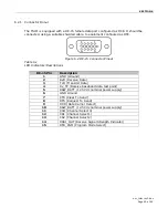
5.2.8 Connector Pin out
DTE connector is a DE-15 female
Figure 5.1 DE-15 Connector Pin-out
Table 5.2
DE-15 Pin Descriptions
DE-15 Pin
Description
1 GND
(Ground)
2 RxD
(Receive
Data)
3
TxD (Transmit Data)
4
Rx_TP (Receive baseband data test point)
5
RAW_BATT (12.5 Vdc nominal power supply)
6 GND
(Ground)
7
CTS (Clear To Send)
8
RTS (Request To Send)
9
DCD (Data Carrier Detect)
10
RAW_BATT (12.5 Vdc nominal power supply)
11
CSO (Channel Select 0)
12
CS1 (Channel Select 1)
13
CS2 (Channel Select 2)
14
RSSI_OUT (Receive Signal Strength Indicator)
15
DTR_PGM (Program Mode Select)
Term
Data
Alternate
Voltage
On Space
Asserted
+3 to +15V
Off Mark
Dropped
-3
to
-15V