Page 13
4.
Adjust the vertical position of the reflected image
using V1 to centre the image. The vertical field aper-
ture size can be adjusted at this point to optimise the
sensor use.
5.
Adjust the vertical height of the transmitted image
using V3 to centre.
6.
Adjust the horizontal position of the transmitted
image using H3 so the outer edge of the image is just
inside the sensor edge. If the images overlap, or there
is a large gap between them, then adjust the horizon-
tal field aperture size to optimise the sensor use, then
readjustment of the split control will allow the outer
edges of the images to be repositioned.
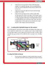
3.5
Locating the OptoSplit images on the camera
If the OptoSplit III controls have been badly misaligned, the images can
show significant aberrations, or in extreme cases only a single image
may be observable for any setting of the ‘Split’ control. In these cases
the following procedure will enable the device setup to be reconfig-
ured.
Locating the Reflected Image
1.
Fit the system calibration cube & shutter the transmit-
ted and centre illumination pathways using the shutter
plates provided.
2.
Define a small area using the OptoSplit input aperture
diaphragm and ensure the input to the OptoSplit is
illuminated.
3.
Attempt to centre the reflected image pathway
horizontally using the ‘Split’ control to scan the
position range.
4.
If no aperture edges can be located for any position
of the ‘Split’control, enlarge the input aperture and
repeat step 3.
5.
Once the image of the input aperture has been
located and centred horizontally, the vertical align-
ment of the aperture can be set using the V1 control.
6.
Adjust the input aperture size so that it just underfills
the camera field of view vertically, and just under one
third of the camera field horizontally.
Locating the Transmitted Image
1.
Move the shutter from the transmitted to the
reflected illumination pathway, the calibration cube
should remain in place.
2.
With the reflected image located, it is likely the
transmitted image will be seen somewhere in the field
of view. If this is the case, small adjustments of the H3
and V3 controls should be used to adjust this image to
mirror the location of the reflected image on the
camera chip.
3.
If no image is seen in the field, we will again scan the
image horizontally. For the transmitted image this is
achieved using the H3 control.
4.
If after scanning the horizontal axis no image can be
found, again open the input aperture slightly & repeat
step 3.
5.
Once the edges of the aperture have been found,
reduce the input aperture as for step 6 above, and
centre the image in the camera field using H3 and V3


