


2-14
Chapter 2: Basic Installation
2.1.9
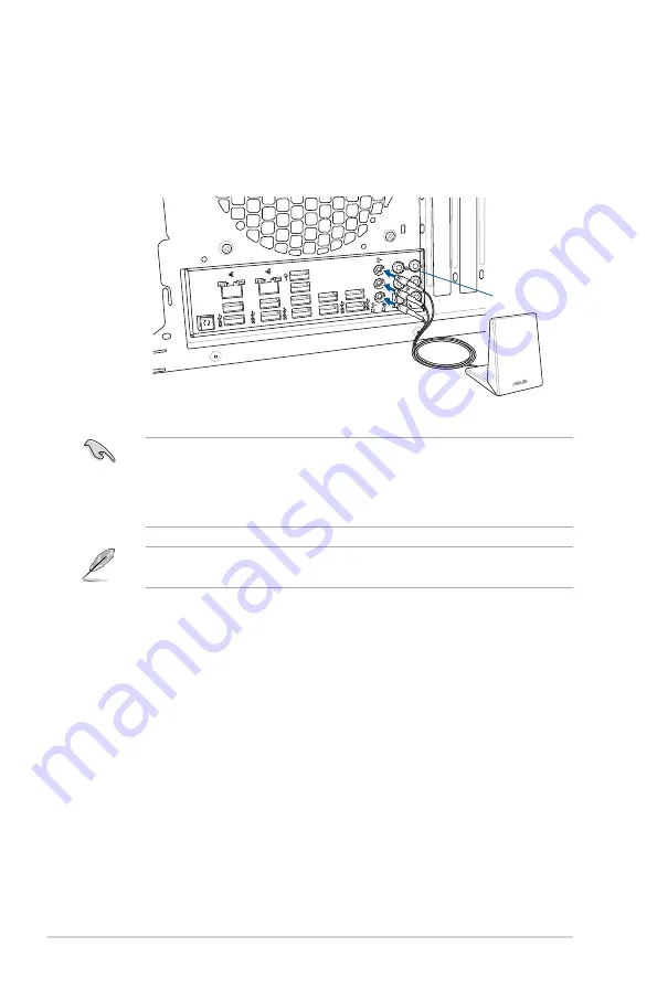
Wi-Fi antenna installation
Installing the 3T3R dual band W-Fi antenna
Connect the bundled 3T3R dual band Wi-Fi antenna connector to the Wi-Fi ports at the
back of the chassis.
•
Ensure that the 3T3R dual band Wi-Fi antenna is securely installed to the Wi-Fi
ports.
•
Ensure to install the Bluetooth driver before installing the Wi-Fi GO! software.
•
Ensure that the antenna is at least 20 cm away from all persons.
The illustration above is for reference only. The I/O port layout may vary with models, but
the Wi-Fi antenna installation procedure is the same for all models.
US
B
BI
OS
Fl
as
hb
ac
k
US
B
BI
O
S
Fl
as
hb
ac
k
US
B
3.
0/
UA
SP
US
B
3.
0/
UA
SP
US
B
3.
0/
UA
SP
US
B
3.0
/U
AS
P
SP
DI
F
OU
T
RE
AR
O/
SU
B
LI
NE
IN
LI
NE
O
UT
M
IC
IN
US
B
3.
0/
UA
SP
BIOS
IO Shield
Summary of Contents for RenderCube XL
Page 36: ...2 4 Chapter 2 Basic Installation Triangle mark Triangle mark...
Page 38: ...2 6 Chapter 2 Basic Installation To remove a DIMM 2 1 4 DIMM installation...
Page 40: ...2 8 Chapter 2 Basic Installation 2 1 6 SATA device connection OR OR...
Page 43: ...RenderCube XL 2 11 To install HYPER M 2 x4 card The SSD card is purchased separately...


