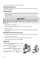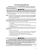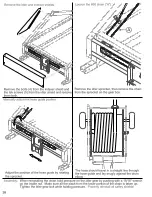
background image

4

APPLICATORS AND ACCESSORIES


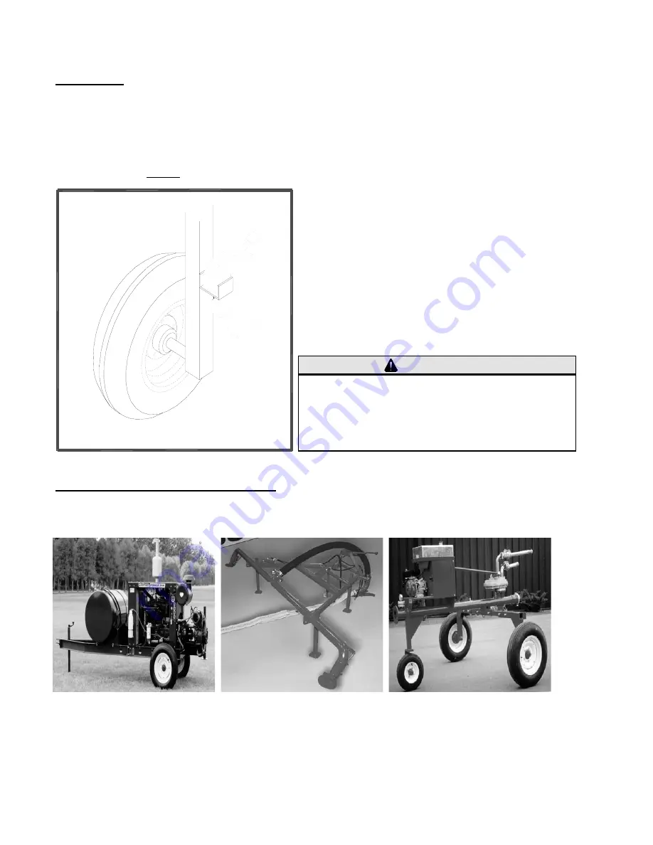
There are a variety of applicators available to be used with your 

Cadman Traveller

.

Ask a 

Cadman Power Equipment Limited 

representative about your options.

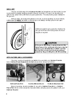
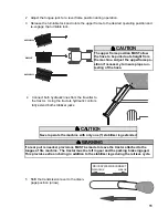
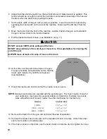
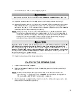
         Cadman Power Pak

          Cadman Manure Boom

 Cadman Broadcast Cart

Many accessories are also available for use with a 

Cadman Traveller

 (i.e. 

Cadman

Power Pak

)  Refer to there respective manuals before using any piece of equipment with your

Cadman Traveller

.

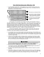
GUN CART


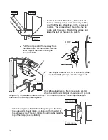
The gun cart assembly of the 

Cadman Traveller

 has adjustable rear track widths as well

as provisions for adding additional weight to the gun cart frame.  The gun cart should be ad-
justed to the widest track width that row spacing will allow.  This will provide greater stability for
the gun cart.

With gun flows exceeding 240 gallons per minute, or when operating on uneven terrain,

additional weight 

MUST


 be added to maintain gun cart stability and help prevent cart upset.

Additional weight may be gained by “loading” the
rear gun cart tires and/or using tractor front end
weights as required.

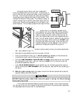
CAUTION

If the gun is set so that it rotates forward of the
rear wheels of the cart (toward the reel), stop the
retrieve cycle NO LESS than 10 FEET out from
the machine in order to prevent gun damage
caused by the gun hitting the cart lift assembly.

Summary of Contents for 3250XL

Page 1: ...3250XL 3750S 4000SA 3750XL 4000S WIDE BODY CADMAN TRAVELLER OPERATOR S and PARTS MANUAL 2001 EDITION...

Page 2: ......

Page 3: ...essories The sole obligation to CADMAN POWER EQUIPMENT LIMITED under this warranty is limited to the repair or replacement of any part it manufactured which in the judgment of CADMAN POWER EQUIPMENT L...

Page 4: ......

Page 5: ...5 Each Use Daily After First 25 Hours Every 50 Hours Every 100 Hours Every 250 Hours 6 Before Storing Before Start Up Lubricants Field Preparation and Operating Tips 7 When Applying Liquid Manure 8 F...

Page 6: ......

Page 7: ...this machine and the safety of operators and spectators whether invited or not 5 Register your machine to validate the warranty Complete and mail the registration card accompanying this manual within...

Page 8: ...tion KEEP ALL SPECTATORS at a safe distance STAY CLEAR of high pressure supply lines especially when first pressurizing the system DO NOT remove or alter any of the shielding from this machine BE CERT...

Page 9: ...ribed in the Required Main tenance section of this manual The shielding MUST be immediately re installed BEFORE putting the machine back in service STABILIZER LEGS All Cadman Travellers are equipped w...

Page 10: ...ons for adding additional weight to the gun cart frame The gun cart should be ad justed to the widest track width that row spacing will allow This will provide greater stability for the gun cart With...

Page 11: ...filter condition 2 Check to be sure that the indexer drive button and connecting link are in good condition Insure that the slide rails are well greased see illustra tion 3 Check the alignment and ten...

Page 12: ...or storage See the storage instructions provided in the Honda engine manual BEFORE START UP After long term storage 1 Review this manual to refresh your memory regarding the proper operation of this m...

Page 13: ...ally The side to side movement of the cart should be no more than the width of the cart s rear wheels 2 If you typically hill your row crops and plan to leave open travel lanes hill and cultivate your...

Page 14: ...ntake rate of some soils Great potential benefit lies in using the nutritional value of the product being applied to replace some or all of the traditional chemical fertilizer used Application timing...

Page 15: ...tacked together all across the base layer of hose Check the position of the hose guide in relation to the hose If the hose does not travel straight through the hose guide and lay snugly against the dr...

Page 16: ......

Page 17: ...jacks WRONG RIGHT WRONG CAUTION The upper frame position MUST allow the hose to be pulled out straight from the machine Adjust the upperframe po sition if necessary to insure proper un reeling of the...

Page 18: ...cart passes see illustration 11 Check the nozzle size and check that the nozzle cone is secure 12 Remove the tractor from the gun cart and clear the area of operation 13 Connect the feeder hose to the...

Page 19: ...ns START UP OF THE RETRIEVE CYCLE 1 Check the engine oil and fuel levels 2 Open the fuel valve on the engine move the ON OFF switch to the ON position and start the engine NOTE If after several attemp...

Page 20: ...of the ramp see illustration START POSITION SECOND POSITION RUN STOP SHUT OFF SWITCH To check the shut off switches lift the shut off bar to a vertical position while manually holding one 1 of the tw...

Page 21: ...on As the hose is un spooled to prepare for the next irrigation cycle the compensator frame will follow the hose level At this time the compensator control cable the cable drive arm and the pulley cam...

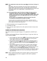
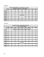
Page 22: ...hine s function to insure proper operation EXAMPLE OF RETRIEVE RATE SELECTION Determine the retrieve rate required to apply a 1 25 application to a field 300 feet in width A 4000 S model traveller is...

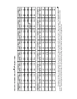
Page 23: ...I GPM DIA GPM DIA GPM DIA GPM DIA GPM DIA GPM DIA GPM DIA 50 100 250 130 270 165 290 205 310 255 330 300 345 350 360 60 110 265 143 285 182 305 225 325 275 345 330 365 385 380 70 120 280 155 300 197 3...

Page 24: ...20 30 40 50 60 70 82 104 CHART 5 RETRIEVE RATE INCHES PER MINUTE MIN LANE SPACING FEET ACRE 200 225 250 275 300 325 350 375 400 10 139 131 15 139 126 116 107 100 93 87 20 131 116 104 95 87 80 75 70 6...

Page 25: ...PARTS SECTION 3250XL 3750S 4000SA FROM SERIAL NUMBER 2559908_ _ _ _ _ 3750XL 4000S WIDE BODY FROM SERIAL NUMBER 2400007_ _ _ _ _ _ _...

Page 26: ......

Page 27: ...36 37 7 Variable Speed w Compensation Cam Assembly P N 40 316 A 38 39 7 Variable Speed Pulley Spring Loaded P N 40 314 40 41 Stabilizer Jack 42 43 3000 Series Gun Cart Assembly Extra Low Clearance 28...

Page 28: ......

Page 29: ...331 1 25 Bolt 3 4 x 2 Lg 90 BLT 07510X200 4 Single Axle 26 Bolt 3 4 x 4 1 2 Lg 90 BLT 07510X450 2 7 Wheel Ass y Consisting of 55 050 2 27 SAE Flatwasher 3 4 90 WSR SAE075 2 Tire 12 5L 15 8 PR Tubeless...

Page 30: ......

Page 31: ...4 1 Decal 3750S 40 280 3750S 10 3 16 Neoprene Fuel Line Tank 40 066 3 Decal 4000SA 40 280 4000SA 3 16 Neoprene Fuel Line Engine 40 066 9 Decal 3750XL Wide Body 40 280 3750XLWB 11 1 4 Copper Fuel Line...

Page 32: ......

Page 33: ...0 Ft 50 004 1150 AR 23 Jam Nut 1 2 13 90 NUT JAM050 13 20 PE Hose 4 04 ID x 1250 Ft 50 004 1250 AR 24 Locknut 1 4 20 90 NUT LOC025 20 1 4 Flanged Hose End 3250XL 07 620 1 25 Locknut 3 8 16 90 NUT LOC0...

Page 34: ......

Page 35: ...WSR SAE063 3 10 Sprocket 60B10 x 1 10 SPT 60B10X100 2 31 SAE Flatwasher 1 90 WSR SAE100 AR Sprocket 60B11 x 1 3250XL only 10 SPT 60B11X100 2 32 Lockwasher 1 2 90 WSR LOC050 6 11 Sprocket 50B33 x 1 32...

Page 36: ......

Page 37: ...4000S WB 40 227 1 36 Decal Danger Rotating Drum 40 287 1 10 Cable Bellows 40 302 1 37 Decal Grease Point 40 041 1 11 Ball Joint 1 4 28 40 226 1 38 Decal Warning Moving Parts Hazard 40 290 2 12 Driven...

Page 38: ......

Page 39: ...4000S WB 40 227 1 36 Decal Danger Rotating Drum 40 287 1 10 Cable Bellows 40 302 1 37 Decal Grease Point 40 041 1 11 Ball Joint 1 4 28 40 226 1 38 Decal Warning Moving Parts Hazard 40 290 2 12 Driven...

Page 40: ......

Page 41: ...SCR RM0632X175 4 6B Machine Screw 6 32 x 1 1 4 Lg 90 SCR RM0632X125 2 7 Locknut 6 32 90 NUT LOC006 32 6 8 Tek Screw 1 4 x 1 Lg 90 SCR TEK025X100 2 9 Flatwasher 1 4 Nylon 90 WSR NYLON025 2 10 SAE Flat...

Page 42: ......

Page 43: ...WSR SAE031 5 10 Engine Mount 40 285 4 39 Lockwasher 1 4 90 WSR LOC025 3 40 Hex Nut 1 4 20 90 NUT HEX025 20 1 11 Control Knob 40 220 1 41 Locknut 1 4 20 90 NUT LOC025 20 1 12 Jam Nut 1 2 13 90 NUT JAM...

Page 44: ......

Page 45: ...g 90 BLT 03816X225 2 9 Shift Fork 40 221 1 33 Spacer 3 8 x 1 3 4 Lg 40 183 2 10 Shifter Handle 40 222 1 34 Brake Handle 40 179 1 11 Clevis Pin 5 16 x 1 1 4 Lg 90 PIN CL031X125 2 35 Spacer 1 2 x 2 1 2...

Page 46: ......

Page 47: ...074 1 8 Control Stem 40 316 207 291 1 9 Snap Ring 40 316 3334 1 10 Cam Bearing 40 216 BRG6205 1 11 Cam 40 243 99 1 12 Jam Nut 1 4 20 90 NUT JAM025 20 1 13 Cable Torque Arm 40 243 2588 1 14 Nylon Ring...

Page 48: ......

Page 49: ...ot Serviced 1B Adjustable Pulley Face Not Serviced 2 Spring 40 128 A 107 032 1 3 Spring Cap 40 128 A 107 033 1 4 Shaft Not Serviced 5 Special Key 40 128 2195 1 6 Retaining Ring 40 128 2243 1 7 Plug Ad...

Page 50: ......

Page 51: ...Stabilizer Jack Drop Leg 07 624 4 Jack Handle 40 176 E 5 Jack Screw 40 176 F 6 Thrust Bearing 40 176 H 7 Bevel Gear 16T 40 176 K 8 Roll Pin 6mm x 36mm Lg 9 Shim Washer 10 Bevel Gear 32T 40 176 J 11 Sq...

Page 52: ......

Page 53: ...5 6 ft 35 Wheel Bearing 55 004 2 14 Galvlanized Shackle Clevis 3 8 40 064 2 Wheel Bearing Race not shown 55 003 2 15 Gun Cart Tow Clevis 02 220 1 36 Hub 4 Bolt 55 002 A 1 16 3 Drain Cap 02 223 1 37 Du...

Page 54: ......

Page 55: ...2 Lg Cotter Pin 90 PIN CT019X200 1 9 Hose End Gasket 02 216 A 1 Hub Assembly 55 002 1 10 3 Drain Cap 02 223 1 Consisting of 11 Gun Cart Tow Clevis 02 220 1 30 Grease Seal 55 006 1 12 3 8 Galvlanized S...

Page 56: ......

Page 57: ...CT019X200 2 10 Gasket Hose Flange 02 216 A 1 11 3 Drain Cap 02 223 1 Hub Ass y Consisting of 55 002 1 34 Grease Seal 55 006 1 Cart Tow Chain Consisting of TR CRT TOWCHAIN 35 Bearing Cone Inner 55 004...

Page 58: ......

Page 59: ...1 7 Wheel Ass y Consisitng of 55 036 1 26 3 4 1 4 Reducing Bushing 40 NPT RB075X025 1 Tire 480 x 8 5 Rib 55 037 1 Wheel Rim 8 x 3 75 x 4 Bolt 55 038 1 27 Bolt 3 8 x 1 1 2 Lg 90 BLT 03816X150 8 Valve S...

Page 60: ......

Page 61: ...x 1 1 2 Lg 90 BLT 03816X150 8 5 Bearing Cone Inner 55 019 1 29 Flange Head Bolt M10 x 20mm 90 BLT FM10150X020 4 Bearing Cup Inner Not Shown 55 020 1 30 Fender Washer 1 4 90 WSR FEN025 36 6 Wheel Hub i...

Page 62: ......

Page 63: ...10 CHN_50 2RIV 14 12 Connecting Link 50 2 10 LNK 50 2CONN 1 13 Gear H50 14 3 4 10 SPT 50B14X075 1 14 3 16 SQ x 1 1 8 Lg Key 90 KEY SQ019X113 1 15 5 5 Hp Honda Engine GX120K1LX 40 159 A 1 16 Gearbox H...

Page 64: ......

Page 65: ...20 014 2 15 Pivot R H Thread 20 015 2 16 Pivot L H Thread 20 016 2 17 Shaft 20 017 1 18 2 in inlet seal 20 018 2 19 Ext Retaining Ring 5 8 in S S 20 019 8 20 2 in Taper Bushing 40 467 3 21 2 in Shaft...

Page 66: ......

Page 67: ...Street Elbow Galv 40 NPT ELS075X90G 2 8 3 4 NPT x 3 4 Hose Barb Galv 40 NPT BRB075G 2 9 Gear Clamp HS 08 50 024 2 10 3 4 Suction Hose IR HOZ SUC075 15 ft 11 Galv Single Tube Clamp 1in 50 058 5 12 Tek...

Page 68: ...Notes...

Page 69: ...quare Inches 10 764 Square Feet 1 ACRE 43560 Square Feet 4047 Square Meters 0 4047 Hectare 1 HECTARE 107642 62 Square Feet 10000 Square Meters 2 47105 Acres 1 SQUARE MILE 640 Acres 259 Hectares VOLUME...

Page 70: ......
Reviews: