


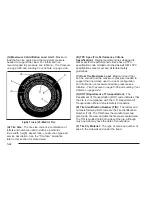


TPM Sensor Identification Codes
Each TPM sensor has a unique identification code.
Any time you rotate your vehicle’s tires or replace one
or more of the TPM sensors, the identification codes
will need to be matched to the new tire/wheel position.
Each tire/wheel position is matched to a sensor, by
increasing or decreasing the tire’s air pressure.
The sensors are matched to the tire/wheel positions in
the following order: left front (LF), right front (RF),
right rear (RR) and left rear (LR).
You will have one minute to match the first tire/wheel
position, and five minutes overall to match all four
tire/wheel positions. If it takes longer than one minute,
to match the first tire and wheel, or more than five
minutes to match all four tire and wheel positions the
matching process stops and you will need to start over.
The TPM sensor matching process is outlined below:
1. Set the Parking brake.
2. Turn the ignition switch to RUN with the engine off.
3. Turn the exterior lamp switch from “Off” to “On”
four times within 3 seconds. A double horn
chirp will sound and the TPM low tire warning
light will begin to flash. The double horn chirp
and flashing TPM warning light indicate that
the TPM matching process has started.
The TPM warning light should continue flashing
throughout the matching procedure. The SERVICE
TIRE MONITOR message will be displayed on
the Driver Information Center (DIC).
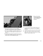
4. Start with the left (driver’s side) front tire.
5. Remove the valve cap from the valve cap stem.
Activate the TPM sensor by increasing or
decreasing the tire’s air pressure for 10 seconds,
then stop and listen for a single horn chirp.
The single horn chirp should sound within
15 seconds, confirming that the sensor identification
code has been matched to this tire and wheel
position. If you do not hear the confirming single
horn chirp, you will need to start over with step
number one. To let air-pressure out of a tire you can
use the pointy end of the valve cap, a pencil-style
air pressure gage or a key.
6. Proceed to the right (passenger’s side) front tire,
and repeat the procedure in Step 5.
7. Proceed to the right (passenger’s side) rear tire,
and repeat the procedure in Step 5.
8. Proceed to the left (driver’s side) rear tire, and
repeat the procedure in Step 5.
5-69
Summary of Contents for ESCALADE EXT 2005
Page 5: ...These are some examples of symbols that may be found on the vehicle v...
Page 6: ...NOTES vi...
Page 16: ...Put someone on it Get it up to speed Then stop the vehicle The rider does not stop 1 10...
Page 139: ...NOTES 3 3...
Page 140: ...Instrument Panel Overview 3 4...
Page 236: ...NOTES 3 100...
Page 408: ...5 110...
Page 414: ...NOTES 5 116...
Page 446: ...NOTES 7 14...
Page 460: ...X XM Satellite Radio Antenna System 3 99 Y Your Vehicle and the Environment 6 2 14...


